 Michael Wessel
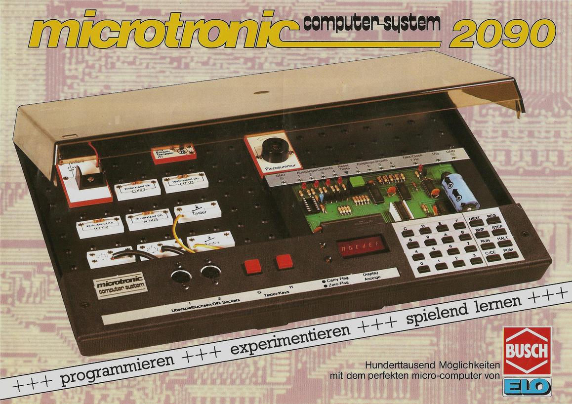
The Busch 2090 Microtronic Computer System was released in 1981 in (West) Germany. It was my first computer on which I learned the basics of (machine language) programming and computer interfacing. This is the original:
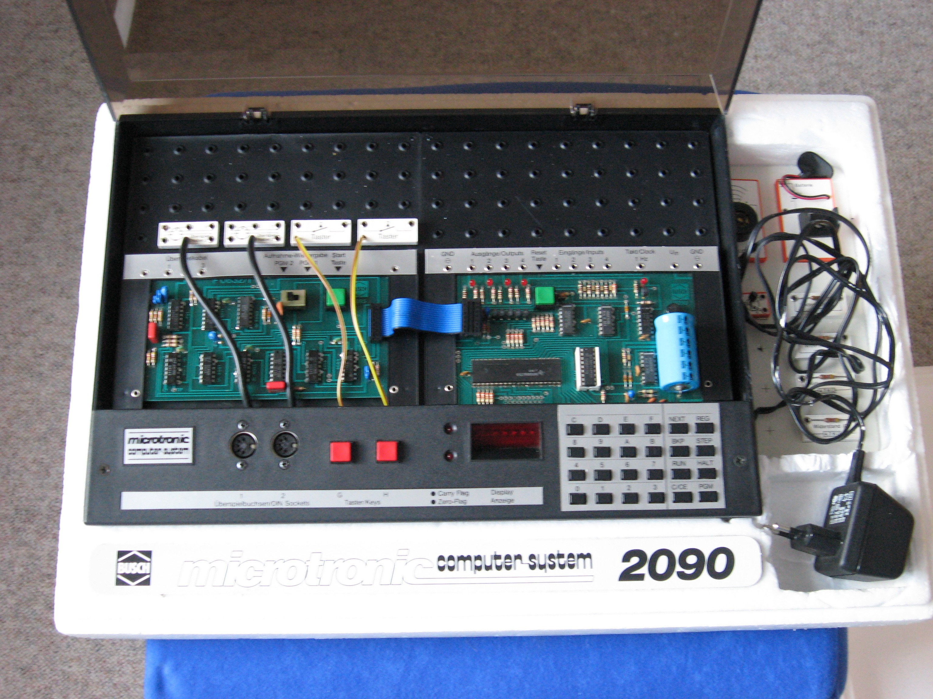
The following picture shows my Microtronic. It was extended with the very rare 2095 Cassette Interface Module (on the left) to allow for cassette tape storage:
In 2016, I had created a talking Arduino-based emulator of the Microtronic system:
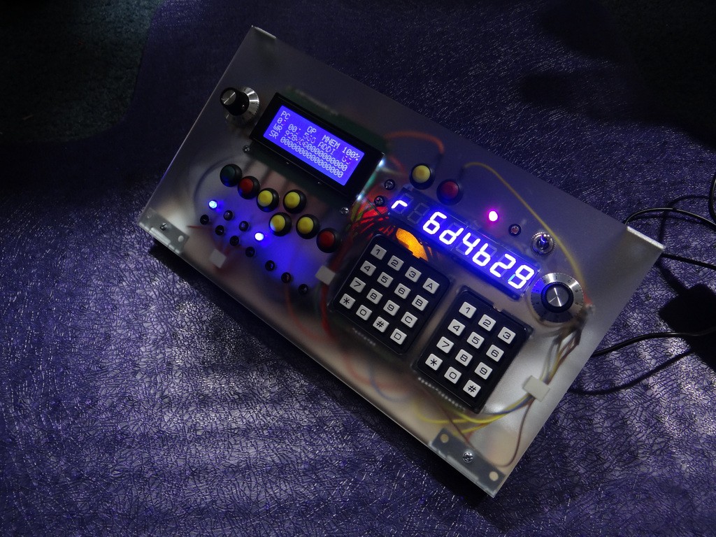
This predecessor project - The Talking Microtronic Emulator - also has a page here on Hackaday. Background info about the Microtronic (i.e., details about its virtual CPU and its instruction set) are provided as well:
https://hackaday.io/project/11560-the-talking-microtronic-computer-system-emulator
Even though the Microtronic uses a TMS 1600 CPU, it was actually not programmed in TMS machine language. Rather, the (mask-programmed) TMS 1600 was running a monitor program that emulated a much more versatile, powerful, and flexible CPU architecture much more suitable for an education system. It even included high-level instructions / op-codes for multiplication, division, time / clock functions, random numbers, display, digital input & output, keyboard input, etc. A very nice instruction set.
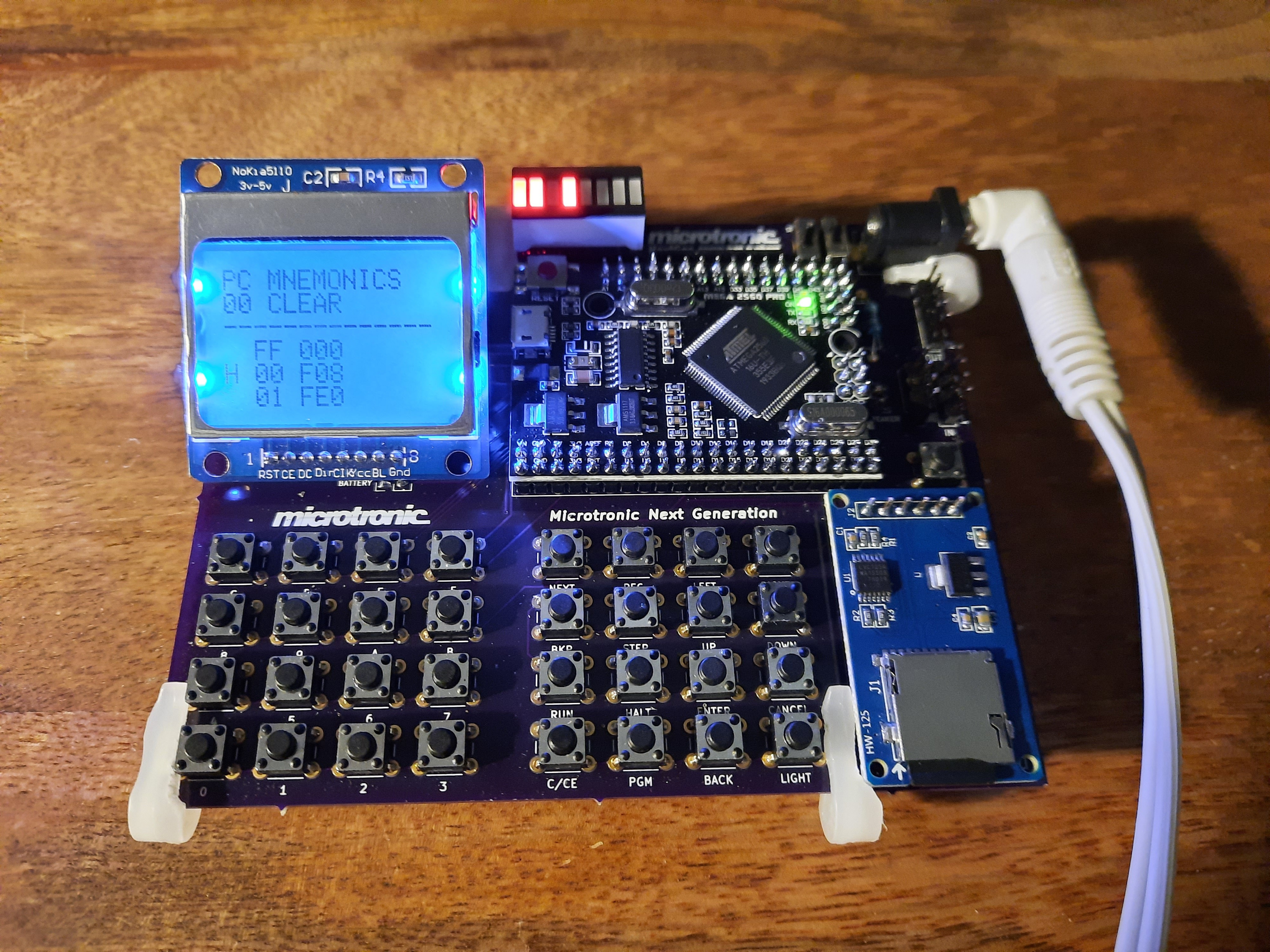
Back to 2020: The Next Generation Microtronic project (these pages) is the continuation, culmination and wrap up of this work. This time, I have a proper PCB with greater reliability and durability than my previous breadboard big-mess-of-wires prototypes, hence preserving my efforts for the future.
PCB Version 1 for the Nokia 5110:
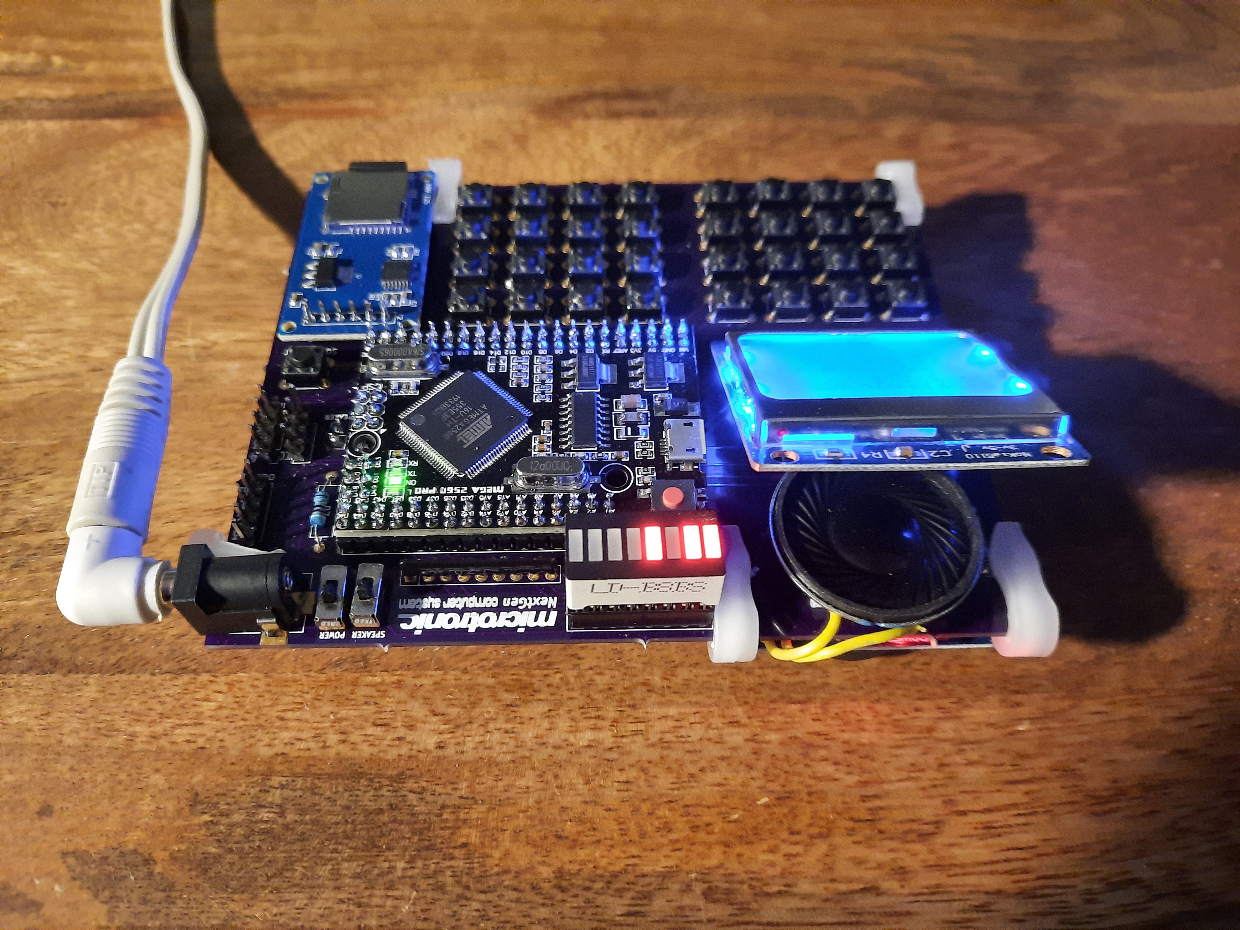
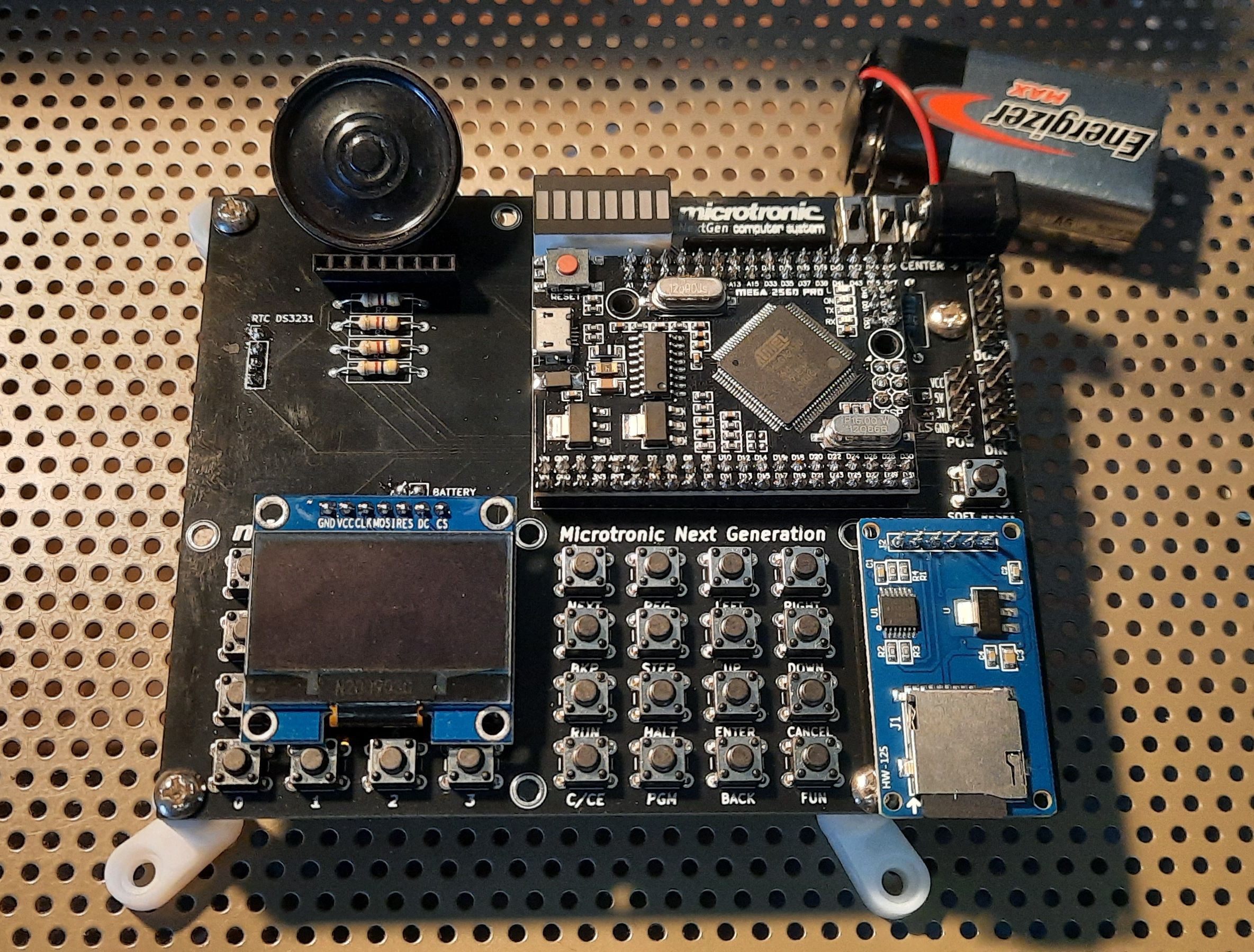
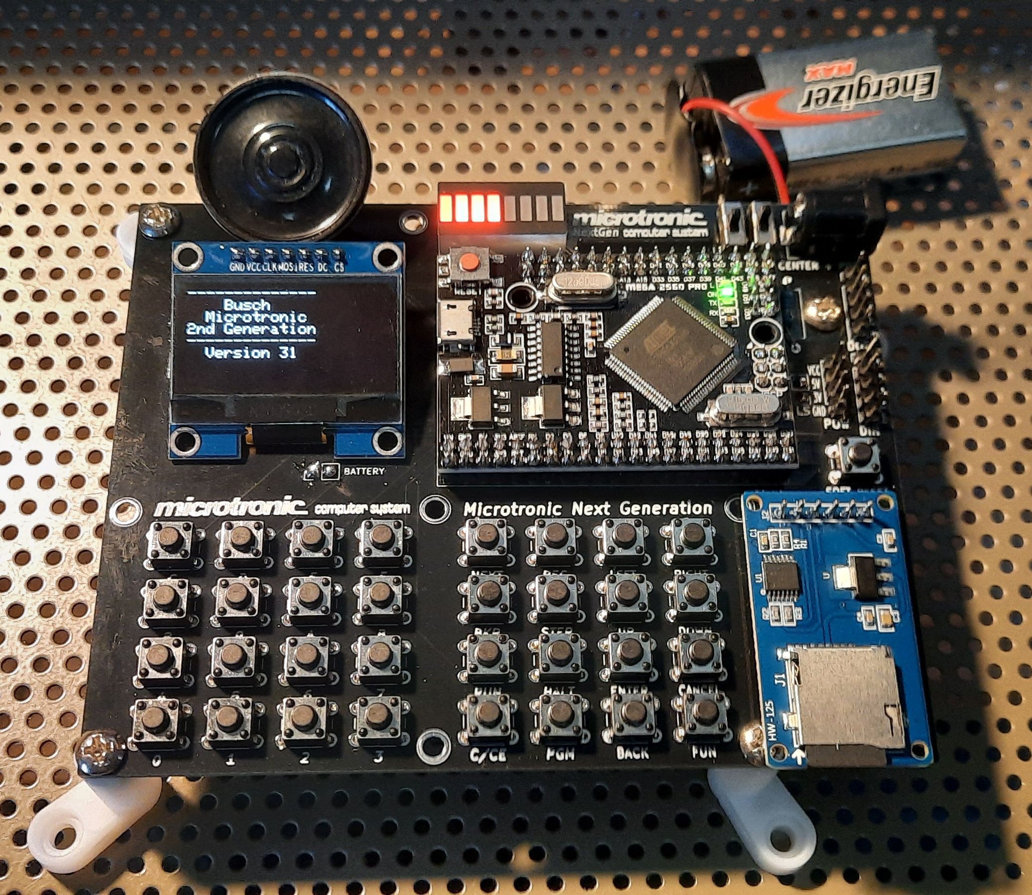
PCB Version 2 for the SH1106 SPI OLED Display:
* Really* Final PCB Version 2 for the SH1106 SPI OLED Display with Pulldown Resistors & Proper Feet:
So, what has changed over the 2016 version? In a nutshell:
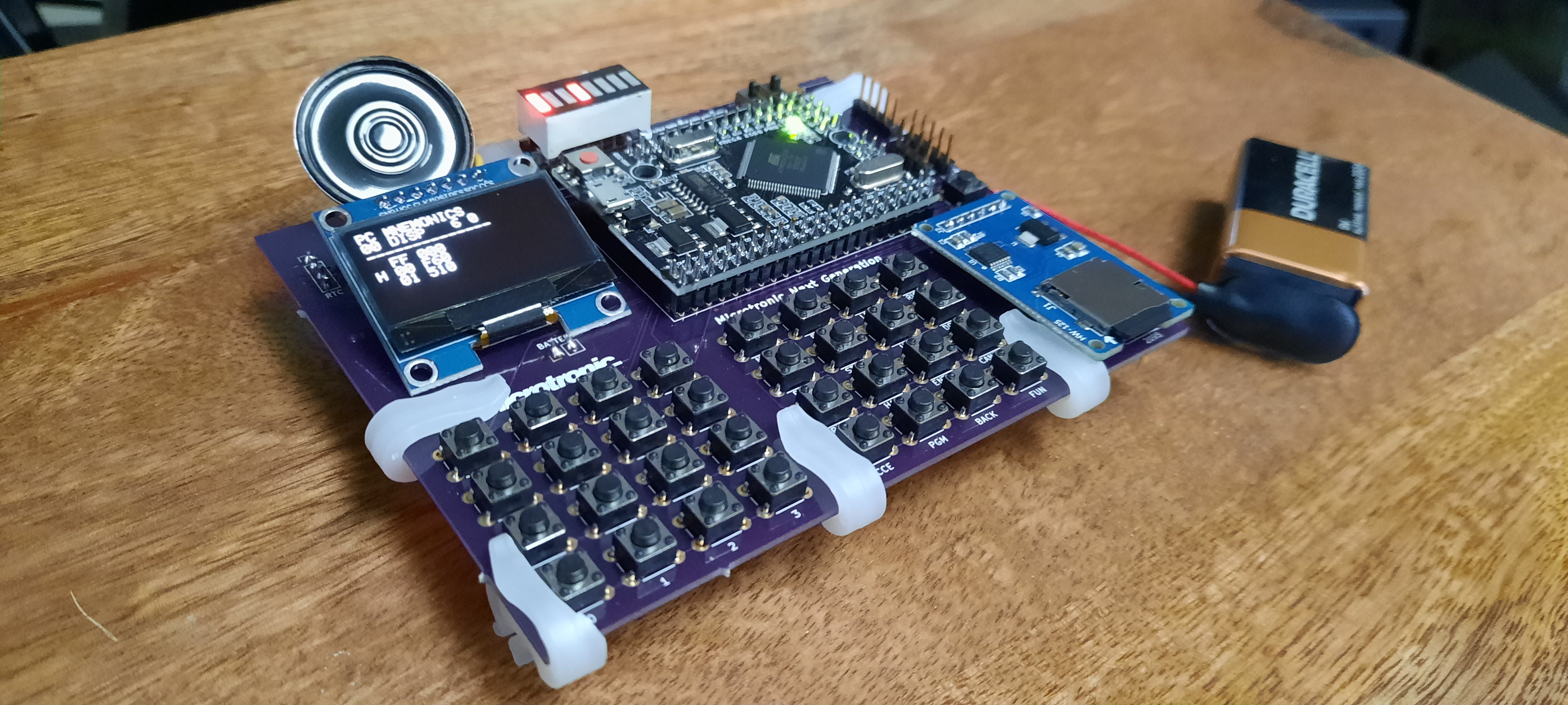
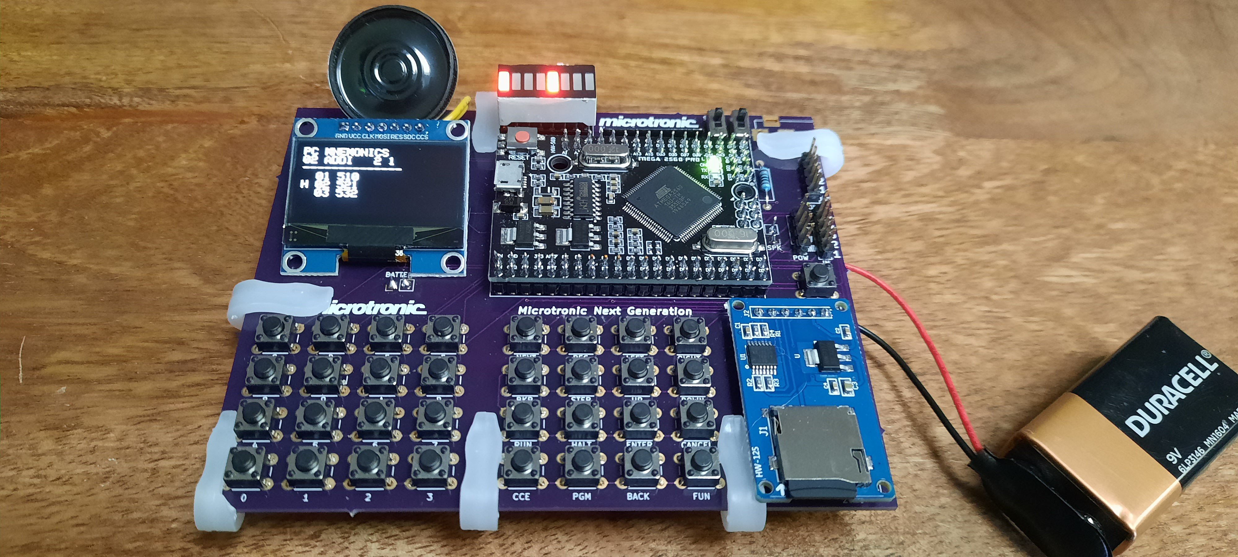
- Nokia 5110 LCD or SH1106 SPI OLED instead of the 7segment LED + Hitachi HD44780 display: the 7segment LED display was nice since it offered a very 1981-like authentic retro user experience. However, a multi-line LCD offering different screen modes that can display mnemonics, multiple addresses of the machine code program at once, etc., has big advantages. Especially for an educational system. A number of display modes are possible: a simple classic one-line Microtronic display, also in double size font; a mode that displays the memory contents (and optionally mnemonics) at the current Program Counter (PC) and its neighborhood locations; a mode that displays the contents of the work and extra-register sets, and so on.
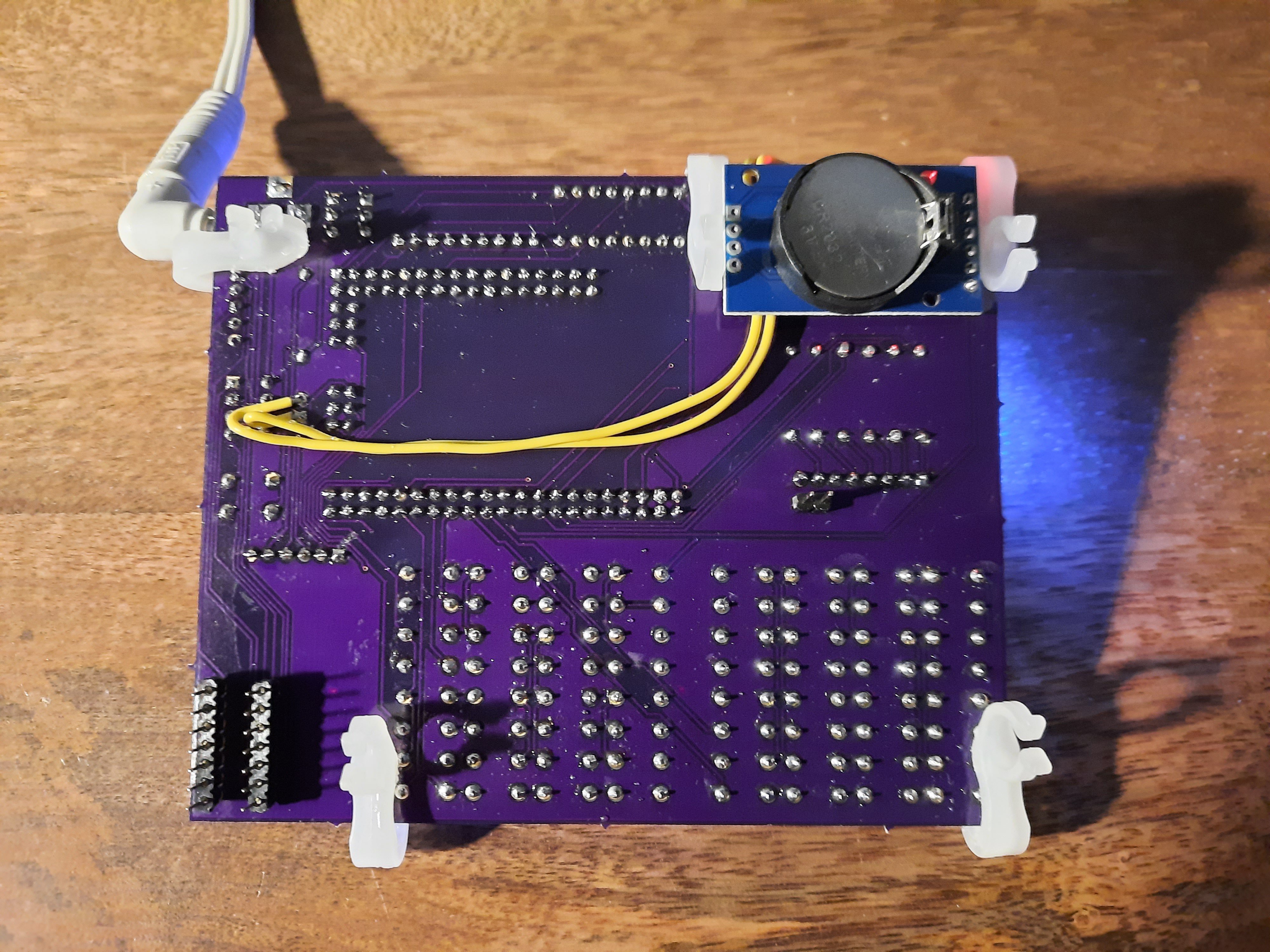
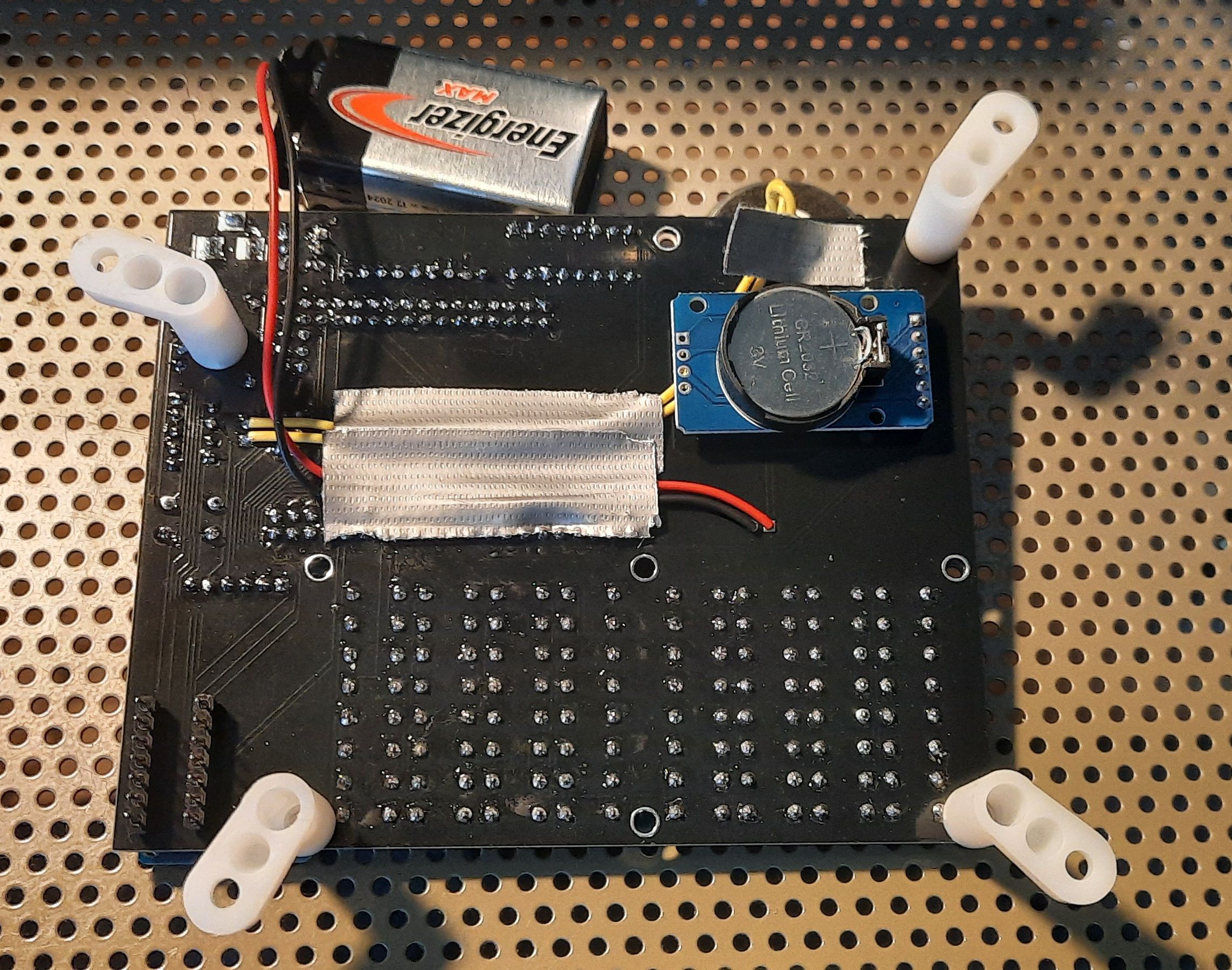
- Real Time Clock: the Microtronic has time / clock functions built in (but no date / calendar). The ROM-program PGM 3 displays the current time, and the ROM-program PGM 4 is used to set the clock. The clock could also be read with a "Get Time" machine code instructions into the registers A to F, so alarm clocks etc. could be implemented. The original Microtronic clock was not battery backed-up though. I have fixed that by linking the PGM 3 and PGM 4 clock functions to a standard DS3231 battery backed-up RTC module. In addition, I have assigned a "set date" function to the built-in ROM program PGM 0. Program PGM 0 usually runs a self-test program, which is not needed here, so it made way for the display / set date function.
- Sound Output: in order to make a sound with the original Microtronic, one usually had to connect a transistor multi-vibrator or a Piezo buzzer to the digital outputs (in the former case, over a simple DA / resistor ladder). However, we figured it would be convenient to have a real SOUND op-code built in. Unfortunately, there are not unused op-codes available in the Microtronic that could be used to this end - every op-code from 000 to FFF is taken and already has a meaning. Fortunately, some of these op-codes are really non-sensensical and hence don't occur in actual existing Microtronic programs. These are the op-codes "MOV x -> x" (copy register x onto itself), "ADDI 0 x" (add 0 to register x), and "SUBI 0 x" (subtract 0 from register x). So, we simply assigned an extra side effect to these existing op-codes - the side effect is to play note "x" on the speaker. This gives us 15 + 16 + 16 musical notes (and "MOV 0 -> 0" for sound off).
- No speech output: unlike the 2016 version, we have no speech synthesizer connected here. Btw, to program the speech synthesizer, we had used the just mentioned "non-sensical" op-codes as well.
- SDcard-based file storage: in a real Microtronic, PGM 1 and PGM 2 are used for Load and Save program from and to cassette tape, resp., via a connected 2095 Cassette Interface expansion. These operations connect to the SDcard interface, like in the 2016 version.
- 2095 Emulation via SDcard file storage: unlike the 2016 version, the PGM 1 and PGM 2 Load and Save Program operations can also emulate the 2095 Cassette Interface! Using an IC pin header at the bottom side of the Next Generation PCB, it can be plugged directly into the Microtronic expansion interface socket and then act as a 2095 emulator. Programs can then be saved from a real Microtronic onto the Next Generation's SDcard, and also loaded back from card into the real Microtronic. The Microtronic Next Generation hence is also of high utility to users of the classic Microtronic that don't own a 2095 Cassette Interface (and which is Unobtainium these days). The Microtronic Next Generation makes a great program library for the classic Microtronic. There are dozens of programs in our Microtronic Next Generation library, in .MIC file format. These programs are plain ASCII, and can hence be created and/or edited easily on a PC using a simple text editor. Microtronic software development has never been more comfortable and dozends of programs are waiting for you!
- Nice 8-Segment Bar-LED Display: from left to right, we have a Power On LED, the Carry and Zero Flags, the 1 Hz LED, and then the 4 output LEDs (DOT 1 to DOT 4). They can put up a good lightshow!
- (GPIO) Input and Output Ports via Headers: like the original, but without any (darlington) transistor drivers or the like. To keep it simple. We also have 5V, 3.3 V, and GND pin headers.
- Soft Reset & Hard Reset Buttons: Soft Reset keeps the memory contents. Hard Reset is on the ATMega 2560 / Arduino board.
- Compact and small design: in principle, it could be powered by a 9V battery. But I haven't tried that yet. I have a pin header on the PCB for the battery though.
- Microtronic Init File: if an SDcard is present, at startup the .INI file is loaded. This contains settings such as default display mode, CPU throttle / speed of the emulation, back-light LED on or off by default, autosave program interval, autostart program name and address, whether key beeps from button pressed are produced, etc.
- Can run from a 9V Battery.
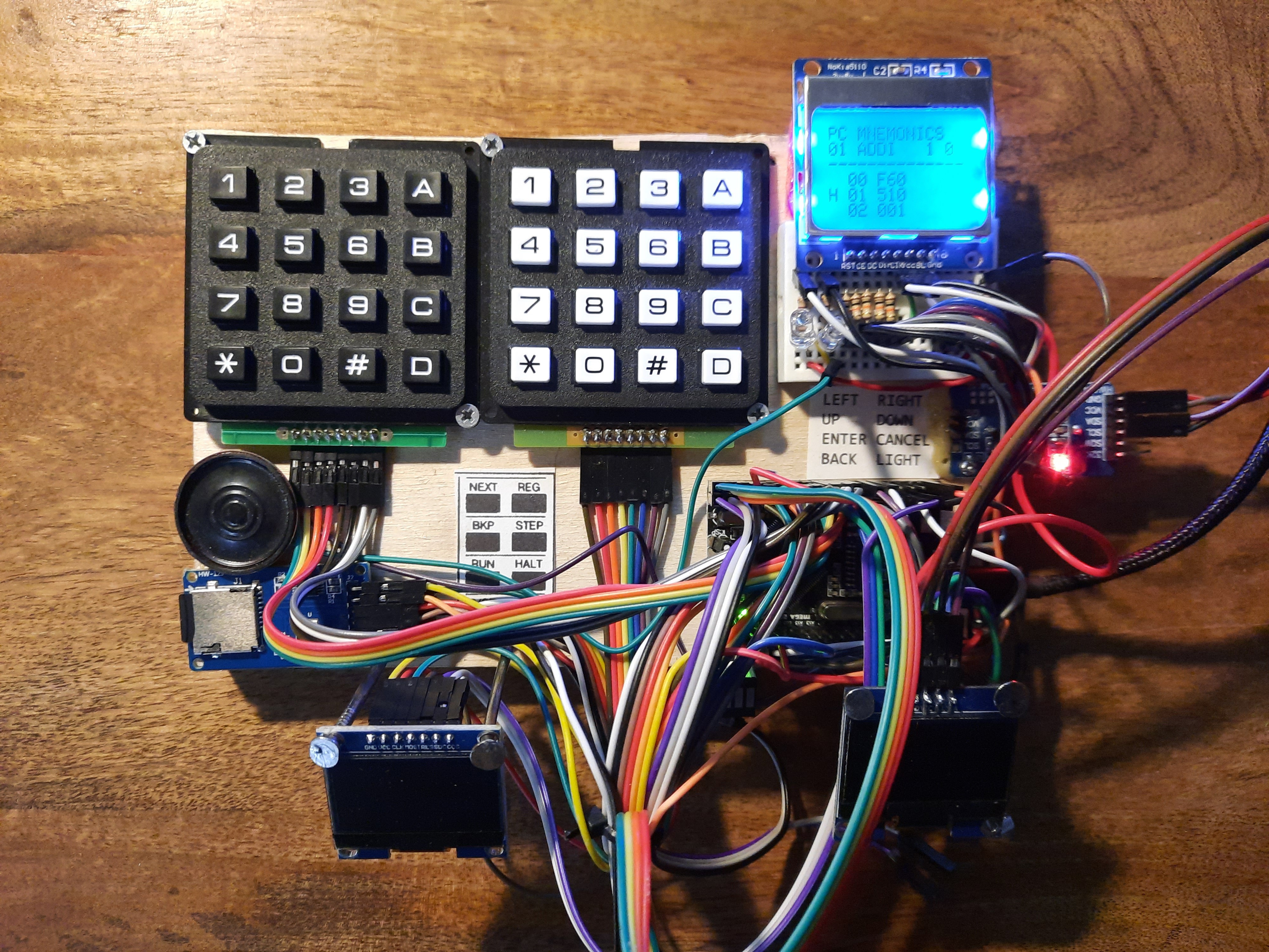
Prototype with 3 different displays for evaluation purposes (Nokia 5110, SH1106 I2C, SH1106 SPI):
Videos:
The GitHub page contains the firmware of the Next Generation Microtronic, for three different displays - the Nokia 5110, the SH-1106 I2C version, and the SH-1106 SPI version:
https://github.com/lambdamikel/Busch-2090/tree/master/microtronic-nextgen-nokia
https://github.com/lambdamikel/Busch-2090/tree/master/microtronic-nextgen-sh1106-i2c
https://github.com/lambdamikel/Busch-2090/tree/master/microtronic-nextgen-sh1106-spi
Which one is best? Well, we actually had to experiment. As we learned in the following video, the SPI version of the SH-1106 is MUCH faster and less laggy than the Nokia 5110, so this is going to be our preferred display for the next iteration of the project:
My renewed interest in this project was triggered by a group of like-minded Microtronic enthusiasts, Frank from Belgium & Manfred from Germany, who contacted me this summer and who invited me to collaborate. We are collaborating (over the internet) on similar projects since Summer 2020.
I am very thankful for the inspiring and fruitful collaboration that we have.
Frank had the idea to use the Nokia 5110 display, and he also suggested to use the ATMega 2560 Pro Mini module instead of the full-size ATMega 2560 that I had used in my 2016 version. He also inspired me to design a PCB for the Next Generation Microtronic (I had mused about this before in order to make the prototypes more durable and professional, but never carried through until now).
Frank & Manfred's Microtronic 2nd Generation professionally installs into a real Busch electronics kit console, and it uses the same firmware (with minor adaptations) as the Next Generation Microtronic / Nokia 5110 version:
https://github.com/lambdamikel/Busch-2090/tree/master/microtronic-nextgen-nokia
More details about the great Microtronic 2nd Generation "sister project" can be found in Frank's YouTube videos:
Please contact Frank & Manfred if you are interested in the Microtronic 2nd Generation project.