 Michael Wessel
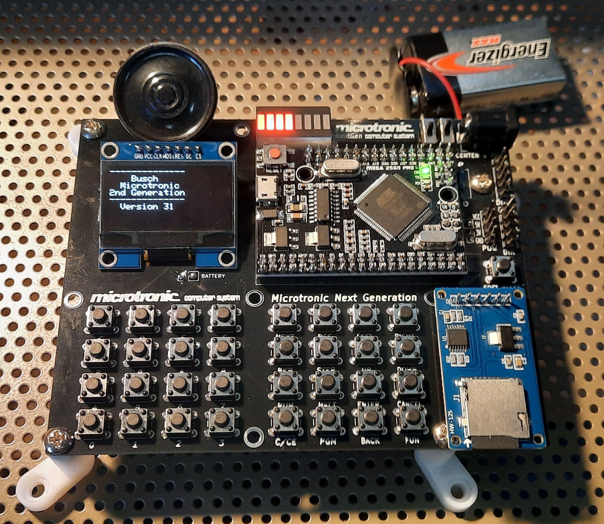
I added pulldown resistors to the digitial inputs to have higher electrical compatibility with the original Microtronic; i.e., electronics experiments as decribed in the Busch manual require non-inverted logic (I was using the internal pullups previously). Ideally, I should have added transistor drivers or at least 2 74LS243 4bit bus transceivers (one for input DIN, one for output DOT). Anyhow, the experiments from the manuals I tried so far all worked; none of them sources or sinks a lot of current into the GPIOs.
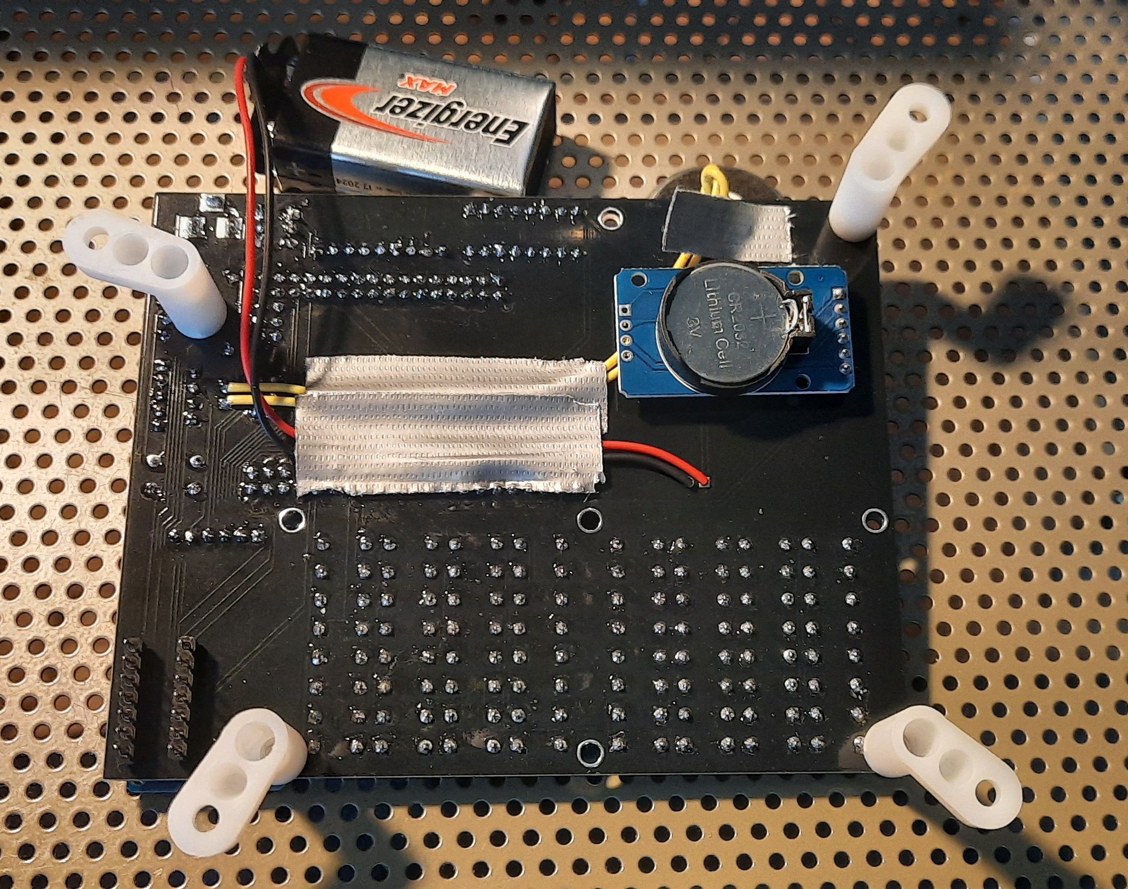
Also, mirror holders from ACE Hardware make a great set of PCB feet! The PCB is final now - OK, a battery holder would be nice... anyhow, there is always something that needs improvement with these projects, and sometimes, good enough must be good enough ;-) I consider the project done by now.

Discussions
Become a Hackaday.io Member
Create an account to leave a comment. Already have an account? Log In.