What it is
SM JogWheel is a jog wheel based on a stepper motor used not as a motor but as a sensor (and as the jog wheel's mechanical guts). A stepper motor like the one used here has magnets and coils that move relative to one another when the output shaft turns. It's this relative motion that produces the cogging -- the bumps in torque -- you feel when you turn an unpowered stepper. It's also the cogging that made such a motor attractive to use in a jog wheel. It gives the wheel a nice feel.
JogWheel plugs into a USB port which it uses to send a sequence of keystrokes and/or mouse events when you turn its wheel, one sequence for clockwise and another for counterclockwise. The more you turn the wheel the more it repeats the sequences. Additionally, you can have multiple sets of sequences and can select which of them to use by clicking buttons on the JogWheel and you can set the sequences with a command-line interface accessed via a serial terminal. The sequences and other configuration information are saved in EEPROM, so nothing's lost when the device is powered down.
How it works
The ends of the stepper motor coils are exposed as the motor's leads. Because it's a motor, the coils and magnets are arranged so that the magnets pass the coils at different times as the shaft spins. This makes it possible to spin the shaft by sequentially energizing and deenergizing the coils with the correct polarity and timing. Here, though, we use the motor's internal arrangement in a different way: Turning the shaft induces voltage pulses across the coils as the magnets pass them. By sensing the number and relative timing of the pulses we can deduce how much the shaft has been turned, and in which direction.
The firmware is for a two-coil, bipolar stepper motor. In these steppers, the ends of its two coils, A and B, are exposed as four wires, A-, A+, B- and B+. When the shaft is turned clockwise, a pulse first appears on coil A and then on B. When it's turned counterclockwise, the pulse on B precedes the one on A. A bit of passive support circuitry cleans up the shape of the pulses, ensures the pulses don't go below about -0.6v and aren't bigger than about 4.5v. (Not surprisingly, the voltage pulses coming directly out of the motor go in both positive and negative directions and get many times bigger as you spin the shaft more quickly.)
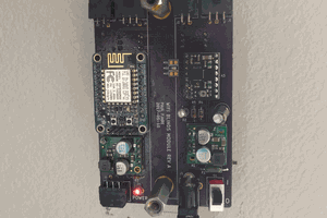
For the microprocessor, I've used an Arduino Leonardo-like board based on the ATmega32U4. This is necessary so that the device can emulate a keyboard and a mouse.
The GitHub repository
In the code repository, the firmware comes tuned for the stepper motor I extracted from my deceased printer, but it should work for any small two-coil bipolar stepper by tuning some of the compile-time constants.
In addition to the code, the repository contains some additional documentation: The schematic for the device itself and a document detailing the way the device uses the microprocessor's EEPROM. I haven't published the laser cutter files for the enclosure because it seems too much dependent on the exact junk rescued parts I used for the project.
 Dave Ehnebuske


 Paul Fjare
 Frank Herrmann
Yes, it can detect a single step. But I can also cause it to miss a single step if I rotate it slowly enough. An experiment I haven't yet tried would be to increase the sensitivity (there are compile-time constants for that) to the point where it starts to see noise and then backing it off.