Close
0%
0%

LED strip flashing to music

Simple circuit for light show

Similar projects worth following
I wanted to build a light show for my room in a student dormitory. We have a lot of parties around here and a flashing LED strip does a good job at creating the mood.

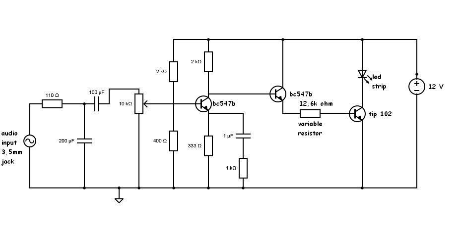
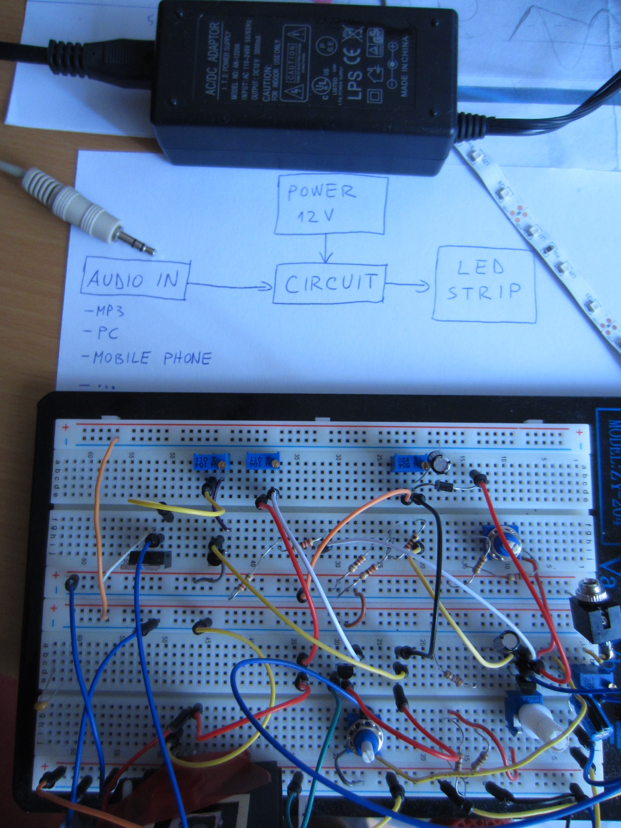
The basic principle of this circuit is amplification of audio signal. And then opening and closing current to LED strip with the NPN transistor. A lot of power is wasted on it, so it needs a heatsink. I have also added a low pass filter, so that LED's flash to the rythm of the music.

I built the circuit on a breadboard. I'm planning to solder it on a perfboard and put it into an enclosure, but I'm waiting for a few parts. Currently I have LED strip with 3528 LED's. I'm planning to buy another LED strip with 5050 LED's, so that they will shine brighter.
To have a better light show, I will add green LED strip with a high pass filter.

Here is video of LED's in action: https://www.youtube.com/watch?v=GBdO7ugAqdI

And in slow motion: https://www.youtube.com/watch?v=Z8UA9_m5amw

System desing:

Audio signal is fed to the circuit. Circuit amplifies the signal with two bc547b NPN-transistors. This signal is then connected to the base of tip102 transistor, which determines amount od current to the LED strip.

Possible problems:
-when I disconnect audio from the circuit, speakers deliver better sound. I don't know how to fix this.
-values of resistors and capacitors could be choosen better. This needs experimenting.

-tip102 could be replaced with higher gain NPN transistor.

-10k potentiometer doesn't work good.

-music on the computer must be at full volume.

I will put this project into an enclosure when I am happy with it. This is not now.

  • 1 × 5m LED strip with 60 3528 SMD leds, 4,8W / m
  • 1 × BC547B transistor
  • 1 × TIP 102 transistor
  • 1 × capacitors, resistors
  • 1 × 12V adaptor, with enough output power

View all 6 components

  • Green LED strip

    mattko08/20/2014 at 09:16 0 comments

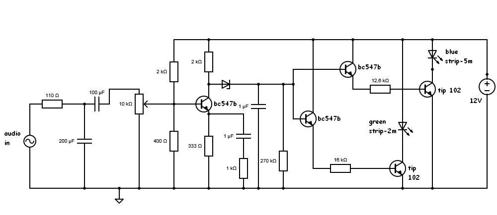
    I added green strip to the circuit. For now it flashes to low tones (same as blue strip).

    Here is the new schematic:

    And another video:

  • Improved brightness

    mattko08/19/2014 at 13:25 0 comments

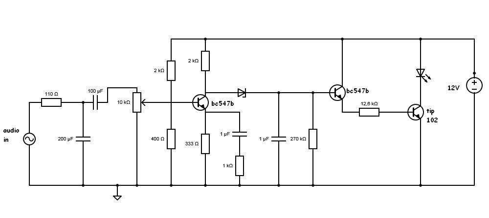
    I succesfully added some components, to make LED's shine brighter. I think it could get a bit better by choosing more appropriate resistor and capacitor, but I would need an osciloscope.

    As a result, strip draws 350 mA DC from the clean sine wave. Here is the upgraded circuit:

  • Changes

    mattko08/12/2014 at 18:34 2 comments

    I made some changes to the circuit for the better. If I feed clean sine wave of maximum volume from the computer, 250mA AC flows through LED's. They draw 1,2A of current connected to 12V. If I connect 5V to the base of the TIP102, LED's draw 560mA of DC.

    So there is still room for more brightness. This is current circuit:

  • Brightness

    mattko08/10/2014 at 11:10 0 comments

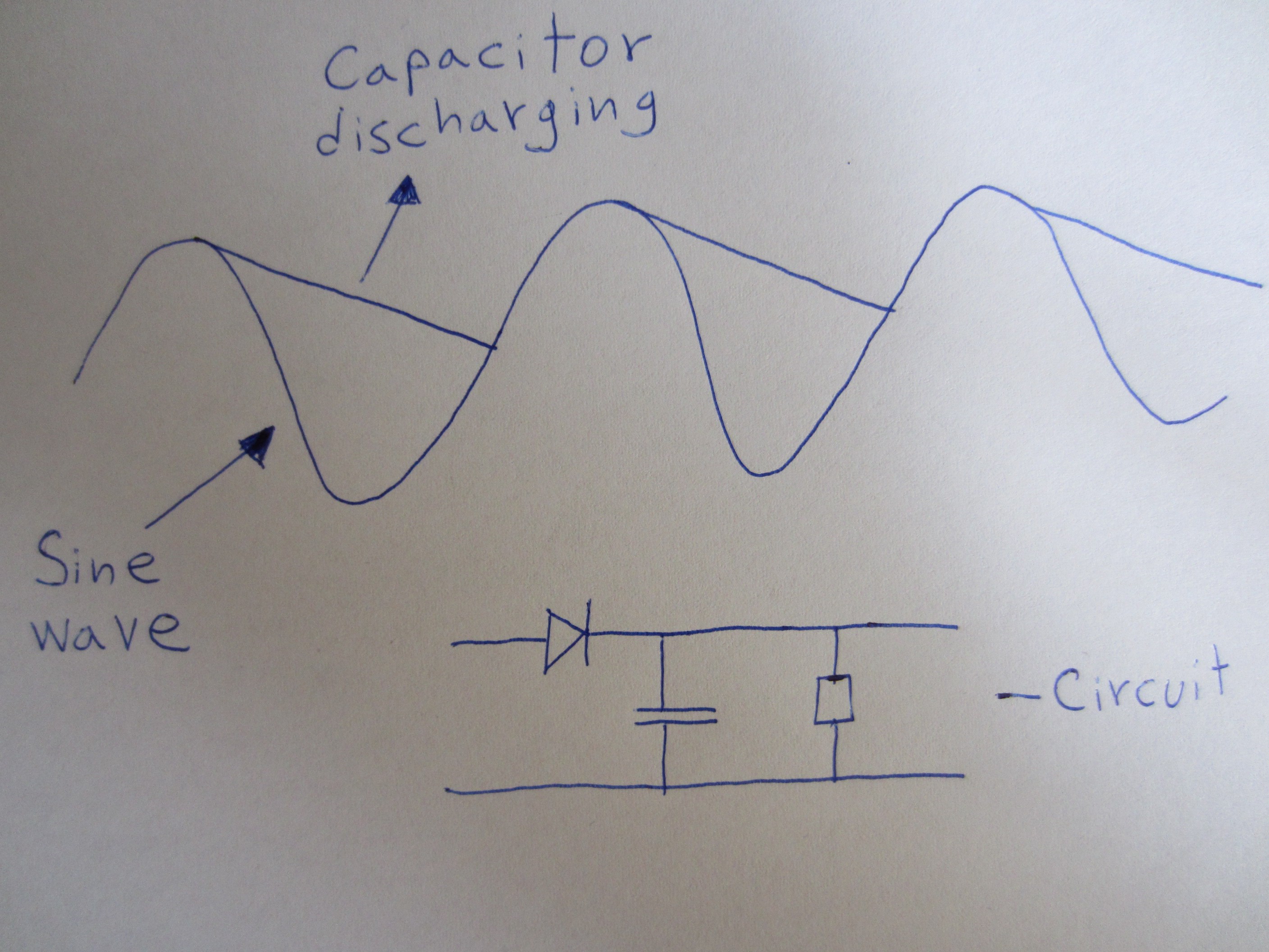
    I am trying to improve the brightness of LED's, so I found out

    that adding this piece of circuit:

    increases brightness, beacuse LED's dont turn on and off fast with 20Hz (Lowest bass), but stay on more time. This is beacuse capacitor gets charged, and then discharged through resistor slower. (see picture). I didn't succesfuly integrated this in my circuit yet.

View all 4 project logs

Enjoy this project?

Share

Discussions

subendu.halder29 wrote 08/25/2016 at 06:22 point

i didn't get the exact values of resistors u used. 110-120, 2k-2.2k, 400-470, tip102-tip122, i built the circuit but its not working. please help me.

  Are you sure? yes | no

Lxhenn wrote 01/11/2015 at 17:33 point

i would use a simple resistor config with a LM833n dual op amp. Almost no wasted power and high speed dds DC pulsed output. Just make a 2 resister voltage divider from your power supply for 0ref.

Search Frex Dig for a simple walkthrough and circuit diagram.

  Are you sure? yes | no

mattko wrote 01/11/2015 at 18:06 point

I improved the circuit, just didn't post anything here-lack of time. The new circuit has input buffer (LM358), low pass filter, non-inverting amplifier(LM358), and that goes to the gate of MOSFET. Works wonderful.

I searched "frex dig", but did not found anything.

  Are you sure? yes | no

ben wrote 04/10/2017 at 14:26 point

I have a similar circuit to your original design and I'm also having problems with noisy audio signal when the lights are on.

Did the input buffer help with noise? Could you share a schematic?

  Are you sure? yes | no

Similar Projects

Does this project spark your interest?

Become a member to follow this project and never miss any updates