John Duffy
-
Ohms is kinda working
09/02/2023 at 04:39 • 0 commentsOhms range is turning out to be a pain. To have some measure of input protection, I'm basiclaly doing a 3-wire sense with the juntion at the positive jack. The ohms "force" has a ~1K resistor, switch, ssr, small fuse, and some low voltage movs. Getting that to be really well controlled would be difficult, so instead I have a known current going into that, the voltage path is high-impedance so most of that goes through the dut, and we just measure the voltage. Instead of an actual current source, it effectively just uses a resistor going to a boosted voltage (~8V above common, but there's significant drop before the output), measure the voltage across said resistor, then we know the current. Hopefully that made some sense, I'll post schematics soon.
I am working to keep down the number of opamps and other actives, kinda for price kinda for accuracy, kinda just because. This has made measuring the voltage drop failrly difficult, the adc only has a range of +-1.5V from common, so I have to do a differential measurement of one low and one high-Z node, which can be from 0 to almost 9V apart, then shift that ~9V down to ground and put it within the adcs range. And the high voltage supply is noisy because it's switched. All of these are fairly simple individually, but getting a setup to handle everything well, without like seven opamps, is challenging (which is half the point of this project anyway, so I'm not taking the easy way out, dammit!).
Anyway it's mostly working using an array of resistors and pfets, and a single opamp and pfet to source a current proportional to the voltage across one of those resistors. That current goes through a smaller resistor to common, which both puts it in the right range and relative to common. Problem is that if there's high voltage across the high-side resistor, there's not enough overhead for both. This still works but requires more range resistors.
Any case I'm mostly accepting ohms range as is for now and moving to putting it all into KiCad, I'll finalize the design and put up schematics soon.
Mean time does anyone knows of a component with a roughly constant voltage drop (looking for about 3V, but could chain a few) even down to the uA range? That would be helpful for this. So like an ideal diode (where "ideal" includes a ~0.7V drop) would work fine by just putting a few in series, problem is real diodes drop goes down close to 0 once you get below a few dozen uA.
-
First Life
08/20/2023 at 06:26 • 0 commentsParts came in, assembled and got the major pieces of the analog front end working together.
This is the input attenuator that allows higher voltages to be measured (up to ~200V right now, but easy to change the ranging), the PGA for measuring smaller voltages (gain is up to x32) and main ADC. Took forever to get the ADC working, spent pretty much all of yesterday working on it but finally got it just now, the switches and PGA only took about an hour to add after that. So at this point, it's got three high ranges (1.5V, 15V and 220V max), and 7 lower ranges. Low (mV) ranges are just gain settings in the PGA, theoretical minimum resolution is about 3uV, but I doubt that will be usable in practice. Shooting for about 0.1mV resolution, but this is still proof of concept so not going to be too worried about it.
The parts I'm using for the ADC is an MCP3461R (16b ADC, up to 1Msps at lower resolution), PGA is an MCP6S28, and the switches are NL7WB66's. Annoyingly I picked out those switches over two years ago for their extremely low off-leakage (typically ~1nA!) which is hard to find, and between ordering them and receiving them, they went last-time buy on Digikey. This ended up being the single hardest part to find, and now I'll have to replace it for any future version. Dang it. Any case I've got a bunch of them on hand and will get through prototyping with this, before I start worrying about a replacement.If anyone else happens to be using the MCP3461 (or MCP3462 or MCP3464 ), for some weird reason, even if you're not using it, the IRQ pin has to be pulled high. Something internal to the device requires this pin to change state to allow the ADC register to be read. AND this is not stated until of the pin description on page 31 of the datasheet (exactly where one WOULDN'T look if they're not using that pin! Why ONLY there?! </rant>
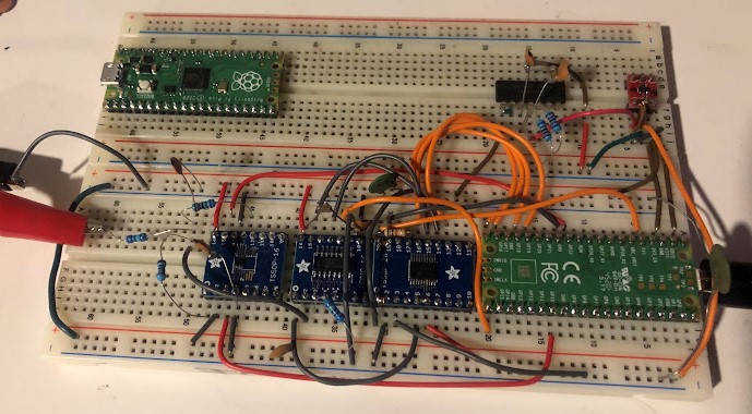
![]()
AFE on a breadboard - far left clips are voltage coming off my power supply to measure, the blue resistors are the input attenuation resistors, the first breakout board is for the switches, middle is the PGA, right is the ADC. A pi Pico is running the show on the right. Top right red board is a separate 3.3V linear reg for the analog supply, and finally the DIP IC with some caps and resistors to the left of that is just an LM324 opamp to split the rail for analog ground (which sits at 1.65V relative to digital ground).
I haven't added the protections, compensation caps or measured the analog bandwidth of this yet, I expect that will actually be fairly annoying since all the parasitics will come out to play. I do plan to have this usable up to a few KHz, should allow for decent peak detection and true RMS calculation, both of which I want to implement at some point.
-
It's not dead!
08/11/2023 at 09:35 • 0 commentsIt's been two and a half years since I updated this, but this isn't dead in the water. Been poking at it but by bit since and finally at a state where I could pull the trigger on the main parts, for the analogy frontend, ADC, and display. Realized supercon is already coming up again and shooting to have something to show by then.