Close
0%
0%

Nixie Clock by TTL/CMOS

Using Nixie tubes and 10 TTL/CMOS standard logics, homemade digital clock has been running continuously for three years

Similar projects worth following
I made a digital clock with Nixie tubes and TTL/CMOS standard logic. Overall, it consisted of simple 1970s technology.
The concept is followings.
(1) It consists of a minimum number of standard logic ICs.
(2) An AC power is used to enable continuous use.
(3) The Nixie tubes are modularized so that they can be replaced.
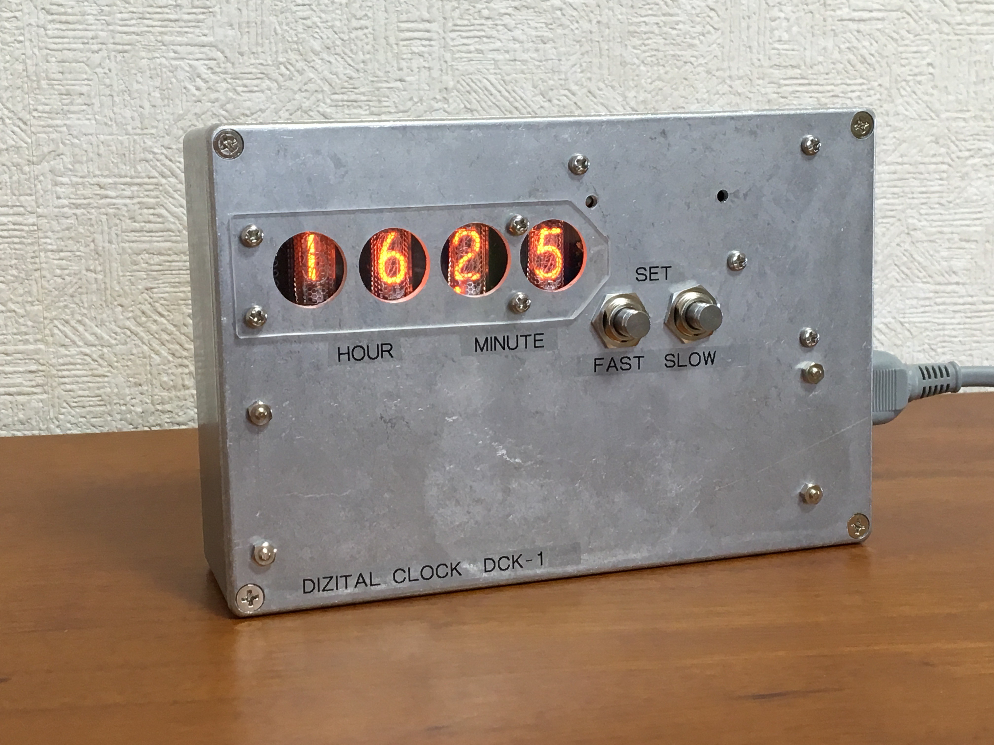
(4) Circuits are built into metal enclosures for long-term safety.
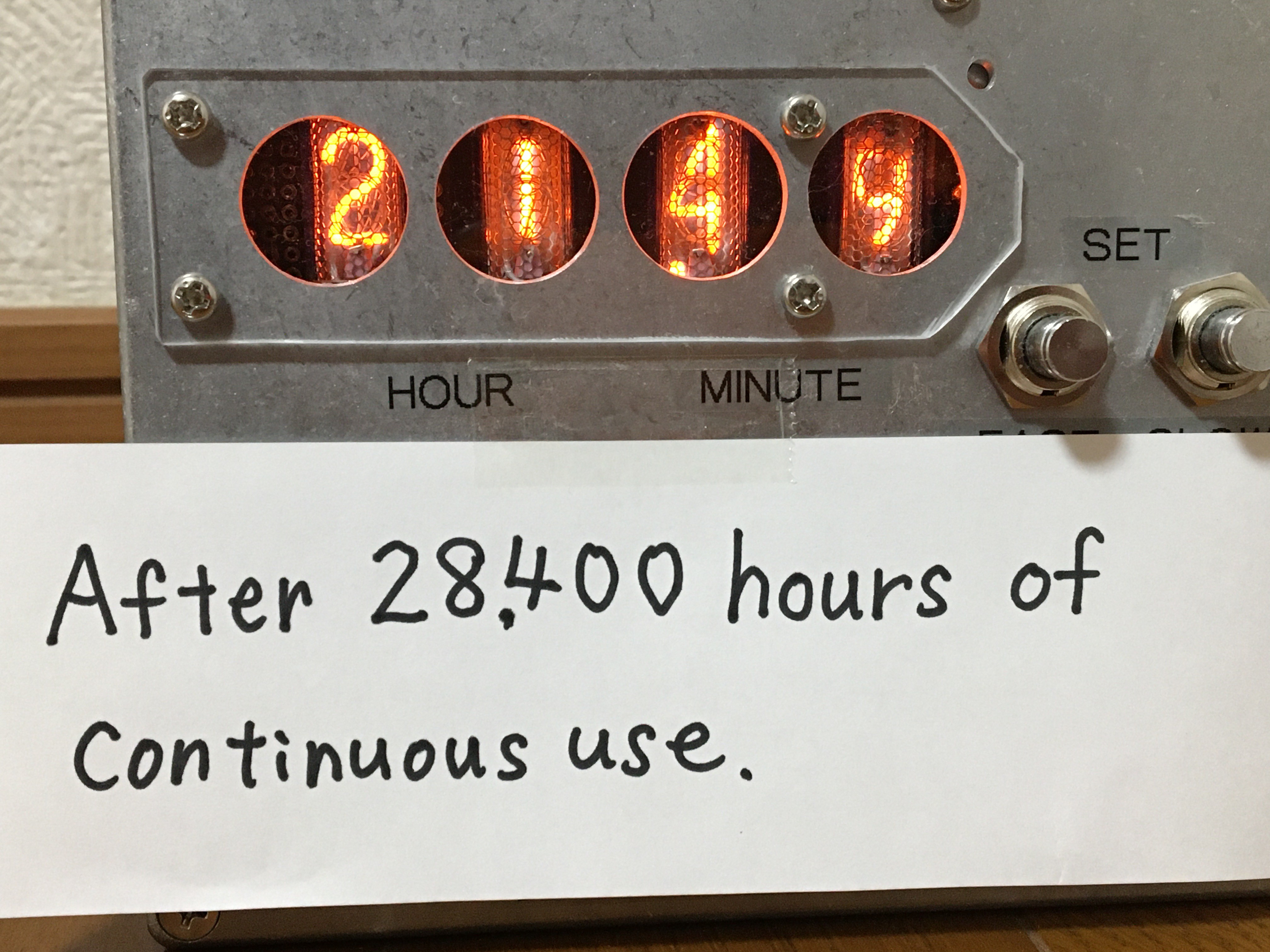
After 28400 hours (3 years and 3 months) of continuous operation, the Nixie tubes are still in the practical range.

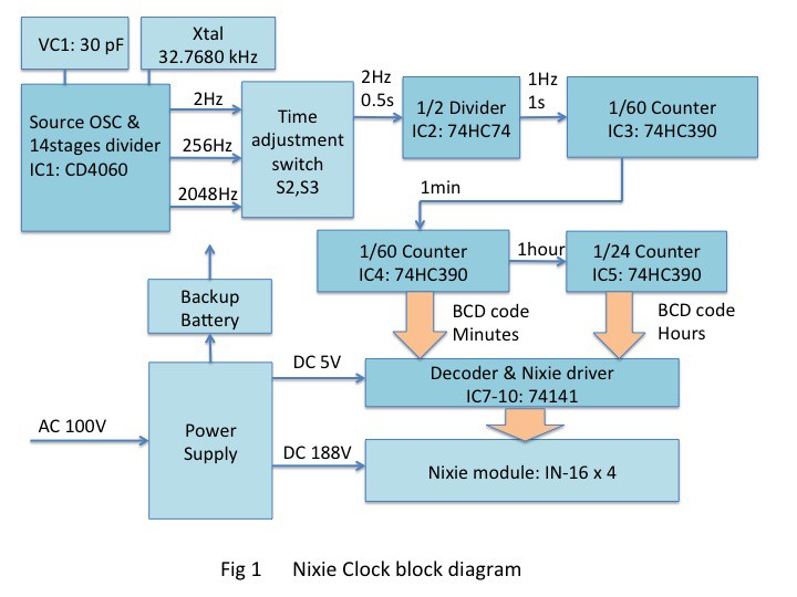
Figure 1 shows the block diagram of the clock. Further details are shown in the attached file schematics.
1. Source oscillator

The source oscillation is performed using an inverter in a CMOS logic IC1(CD4060) and a 32.7680 kHz crystal. Fine-tuning of frequency is done with VC1.

2. Frequency divider

The source oscillation frequency is divided down to 2 Hz (x1) by the 14-stage frequency divider inside the IC1(CD4060). Here, 2048 Hz (x1024) and 256 Hz (x128) switched from 2 Hz signal by a push-button switch when setting the time. A 2 Hz signal is divided by IC2(74HC74) to get a 1 Hz (1 s) pulse.

    A 1/60 counter configured with IC3(74HC390) makes it an 1 s pulse into an 1 minute pulse. Then the 1 minute cycle pulse is counted until 1 hour cycle by a 1/60 counter configured of IC4(74HC390).  In addition, the pulse of one hour cycle is counted by a 1/24 counter configured of IC5(74HC390).

3. Nixie driver

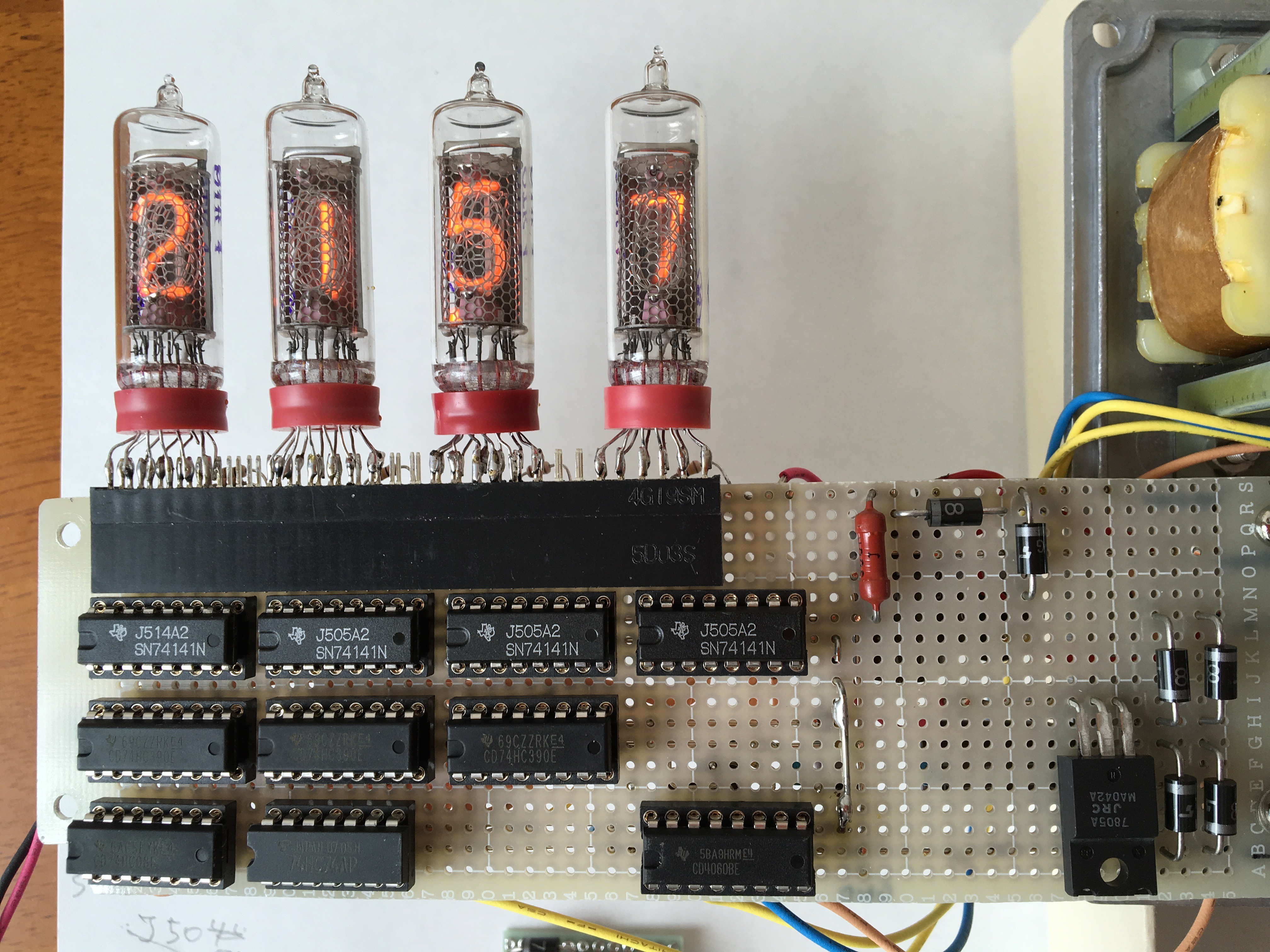
The minute and hour BCD codes output from the counter are input to IC7-10 (74141) BCD-to-Decimal Decoder/Driver.
4. Nixie module

As shown in the photo, four nixie tubes were soldered to a pin header to make a module. The pin header is inserted into the header connector on the board. This allows the Nixie tubes to be easily replaced.
5. Power supply

The 100 V AC power from the AC inlet is converted to 6.3 V AC by the transformer T1 through a fuse. This was then bridge rectified to generate 5 V DC for the IC circuit by the series regulator IC11(7805). The high voltage for the Nixie tubes is 6.3V AC converted to 100V AC by the transformer T2, which is then voltage-doubling rectifier to produce 188V DC. A 50k Ohm resistor was connected to the anode of the Nixie tube, and the anode current was set to a small 1.1mA.

6. Battery backup

IC1-IC6 are backed up by 3.6 V, 70 mA h NiMH batteries so that this clock will not lose time even when the AC power is turned off.

7. Enclosure

The clock uses an 18 cm x 12 cm x 5 cm aluminum die-cast enclosure. This is because to ensure safety in long-term continuous operation.
8. Results

Oscillator adjustment:

I adjusted the frequency to 32.7680 kHz with a frequency counter. If the frequency is off by 0.1 Hz, the error of the clock will be 0.26 s par day.

Time deviation during a year:

The error in this clock over a long period of time is due to the temperature characteristics of the source oscillator crystal. This clock has used in an environment with a minimum temperature of 10 degrees Celsius in winter and a maximum temperature of 35 degrees Celsius in summer.  It keeps the time lag to within plus or minus 30 seconds throughout the year.

Nixie Tube Life:

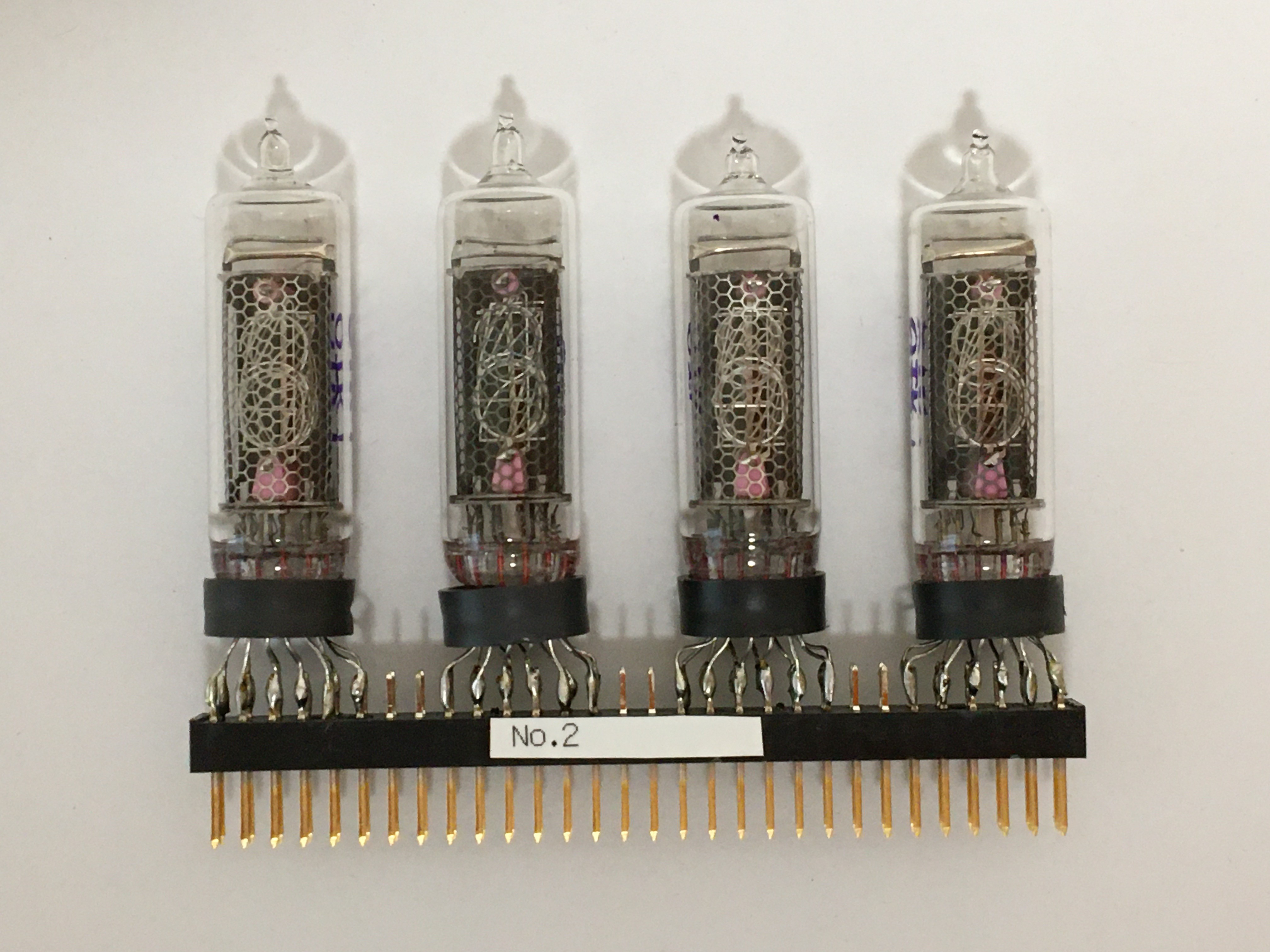
The photograph the display status of the Nixie tube after 28,400 hours (3 years and 3 months) of continuous operation. Some of the characters ‘4’, ’9’, ’8’ are a little chipped, but still in the practical range. 
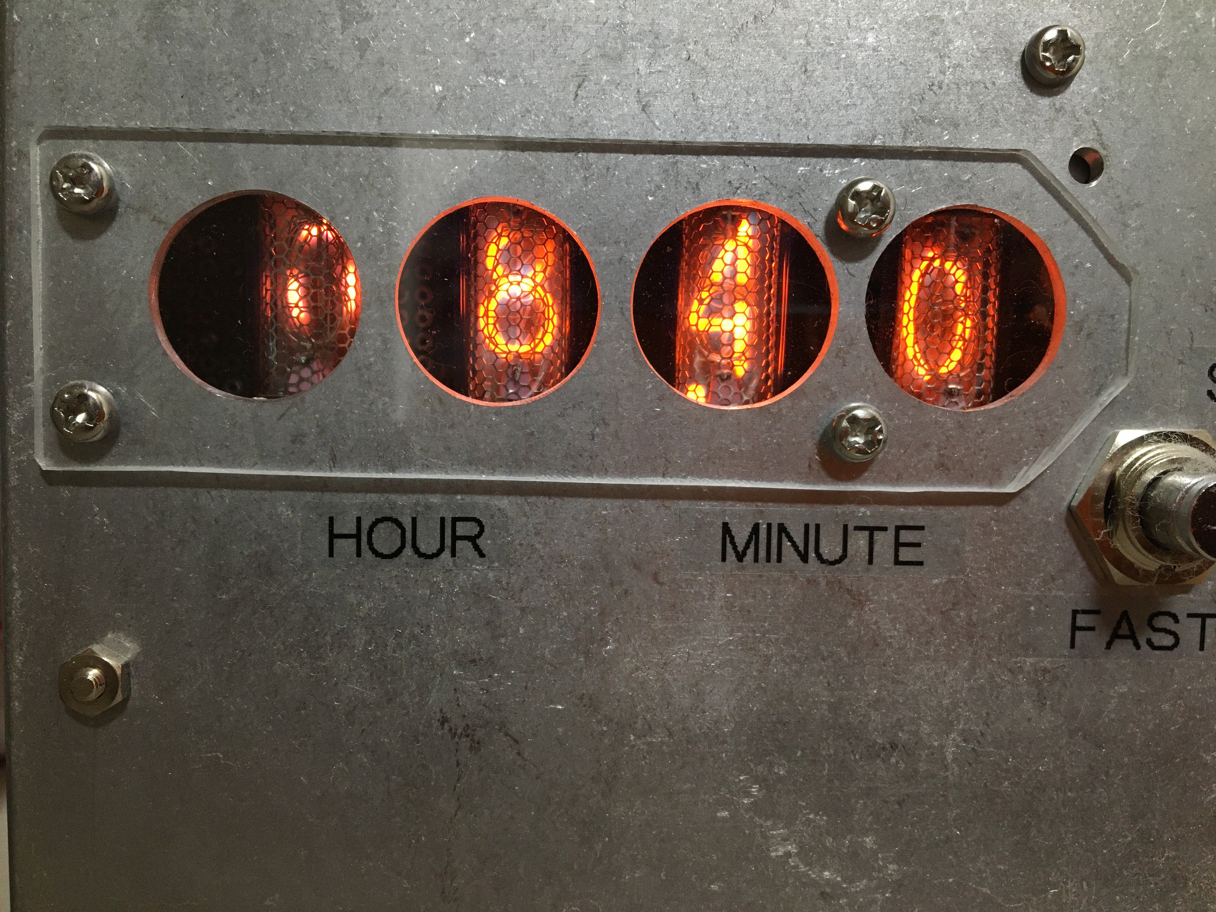
The next photo shows the condition of the display after 50,900 hours (5 years and 9 months). At this point, the display characters had completely lost their shape, so the nixie tube module was replaced with a spare new one. It had a longer lifespan than first assumed.
Video: 

The following video shows the time setting. There is no audio commentary, so please turn on subtitles.


IMG_1140.jpg

Schematics of the Nixie Clock

JPEG Image - 4.98 MB - 01/01/2021 at 07:36

Preview

NIXIE_CLOCK_FIG_001_1 .pdf

Block diagram of the Nixie Clock

Adobe Portable Document Format - 233.74 kB - 01/01/2021 at 07:35

Preview

  • 1 × CD4060 Electronic Components / Misc. Electronic Components
  • 1 × SN74HC08 Logic ICs / Gates and Inverters
  • 1 × SN74HC74 Logic ICs / Flip-Flops, Latches, Registers
  • 3 × SN74HC390 Logic ICs / Counters
  • 4 × SN74141 Logic ICs / Decoders, Encoders, Multiplexers, Demultiplexers

  • Nixie clock project log

    Mitsuru Yamada10/26/2022 at 13:29 0 comments

    1. The article was first posted on Jan. 01, 2021

    2. Revised on Oct. 26, 2022

          Added video link for "Setting the time on a homemade Nixie clock".

    3. Revised on Sep. 05, 2023

         Added the photo of Nixie tube module replaced at 50,900 hours to the result chapter.

View project log

Enjoy this project?

Share

Discussions

michimartini wrote 05/12/2022 at 21:29 point

I really like the circular windows for the nixies. It reminds me of what the ticket vending machines for the public transport in Zurich used to look like. 

  Are you sure? yes | no

Mitsuru Yamada wrote 05/18/2022 at 09:10 point

Thank you very much. Since the enclosure is die-cast aluminum, I was able to drill this holes cleanly with a hand reamer. I never saw Nixie tube displays in town when I was a child in my local city in Japan, but I have a strong impression that the clock characters superimposed on the screen during marathon broadcasts on TV were Nixie tubes.

  Are you sure? yes | no

w_k_fay wrote 01/11/2021 at 20:38 point

Nice clean design. Did you consider using the mains for the oscillator ? I see Japan has both 50 hz and 60 hz mains.

It looks like you have cathode poisoning on some of the digits.

  Are you sure? yes | no

Mitsuru Yamada wrote 01/12/2021 at 01:34 point

Thank you for your comment. At first, I was thinking of the AC mains dividing. However, I had to set the time if I disconnected the mains. I decided to use a crystal oscillator so that the time would not deviate with battery backup even when the mains was disconnected.

28,000 hours of use, the display has gradually deteriorated. I think this is cathode poisoning. It was able to exceed the IN-16 data sheet specification life of 7,500 hours. I'm planning to continue using the module, replacing it every about 5 years. I'll take a look at ’Anti-Cathode Poisoning' websites. 

  Are you sure? yes | no

marazm wrote 01/08/2021 at 14:02 point

meybe add rotor / knob/ big potenciometer for setup.

buttons are not comfortable

  Are you sure? yes | no

Mitsuru Yamada wrote 01/08/2021 at 23:46 point

Thank you for your comment.  In order to minimize the number of standard ICs and switches used as shown in the schematic, I tried setting the time by simply pressing a button to advance the time. It is true that setting the time is a bit tricky. But in my case, I don't need to set the time more than once a year, so it's practical.

  Are you sure? yes | no

Ekspansja wrote 01/07/2021 at 21:15 point

Very nice enclosure. 

Add GPS clock synchronisation 

And offgrid 

  Are you sure? yes | no

Mitsuru Yamada wrote 01/08/2021 at 01:14 point

Thanks! It is a little heavy with die-cast aluminum and power transformers, but it is stable in place.

  Are you sure? yes | no

Dan Maloney wrote 01/04/2021 at 23:24 point

Another great looking project. Love your build style!

  Are you sure? yes | no

Mitsuru Yamada wrote 01/05/2021 at 00:42 point

Thank you. When I made a frequency counter in 1975 for ham radio, Nixie tubes were used generally. I made this so that I could remember those days. 

  Are you sure? yes | no

andybiker wrote 01/04/2021 at 01:37 point

I have a similar clock. all cmos counters. ( I use 4017 and mpsa42 transistors to drive nixies)

It has run 24-7 since about 2001. that's 19 years so far.

Another one been running 24-7 since 2003.

both use ultra-long-life nixie tubes and still look very good!

There's something about using standard components - no microprocessor, no firmware, easy to repair.

  Are you sure? yes | no

Mitsuru Yamada wrote 01/04/2021 at 10:58 point

Thank you for watching.  At 24 hours a day for 19 years, that's about 167,000 hours, the life of your ultra-long-life Nixie tubes are so great. At first I was also thinking of a circuit made with an old 8-bit CPU. However, the number of elements could not be reduced to include the number of Nixie tube drivers and parallel register ICs. The dynamic drive method was too cumbersome to consider, so I decided to simply use standard logic to divide the frequency.

  Are you sure? yes | no

Mitsuru Yamada wrote 01/03/2021 at 13:11 point

In the the text, and caption of the photo, I misspelled 28400 hours as 2840 hours, so I've corrected it now.

  Are you sure? yes | no

Ken Yap wrote 01/01/2021 at 23:55 point

👍 Another solid build. Should last a long time.

  Are you sure? yes | no

Mitsuru Yamada wrote 01/02/2021 at 01:30 point

Thank you for watching ! For a long time of use, it needs to be cleaned of dust, but I found it easy with this design. The nixie tube display is easy to read for when I look at the time in the midnight, and I've been using it conveniently for 3 years.

  Are you sure? yes | no

Similar Projects

Does this project spark your interest?

Become a member to follow this project and never miss any updates