Print the enclosure parts (see Files section), cleaning up the holes on the bottom surface of the body so that a washer and screw head sit below flush from the surface (the flat side will be placed flat against the underside of the desk).
2
Remove and open the control panel.
Unscrew the control panel from your desk.
Open up the control panel case using a dremel, pliers, cutters, and/or a screwdriver as needed and remove the flexible button PCB. BE CAREFUL NOT TO DAMAGE THE PCB! It is only slightly below the control panel case you'll be cutting. IKEA sent me a spare, but shipping takes a while.
3
Solder the boards.
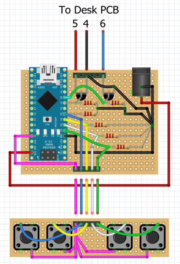
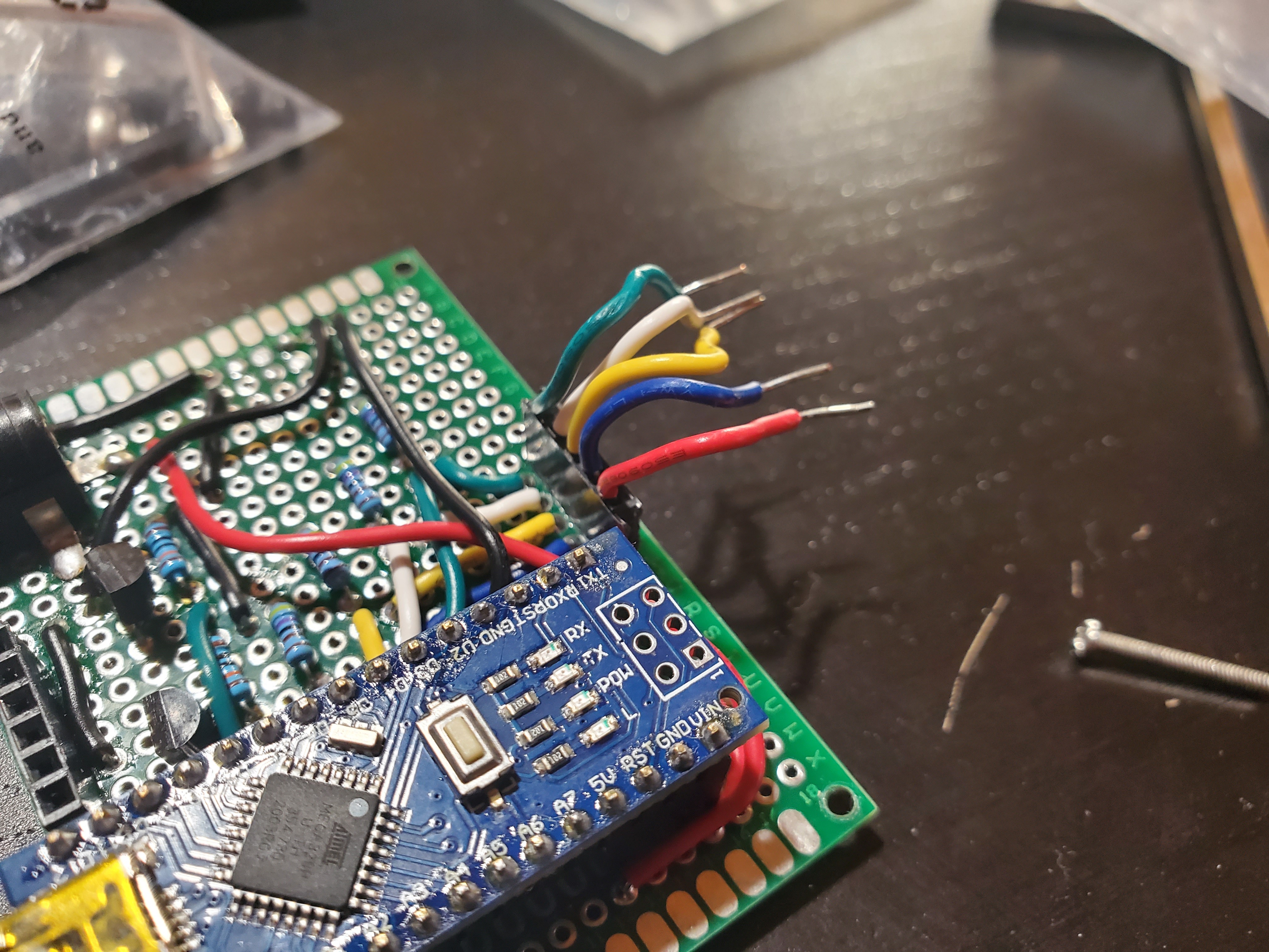
Solder the two boards shown below (What I call the "main PCB" in the video is on top, and the "button PCB" is on the bottom; I realize they aren't technically PCBs, I just want to remain consistent with the video's phrasing). Be sure to add headers underneath the pins of the Nano; don't solder the Nano directly to the board (it makes replacement easier later, if necessary).
The main PCB has 24 columns, 18 rows. The button PCB has 28 columns, 6 rows. All resistors are 220 Ohm. You will have to drill out one of the holes to fit the negative lead of the power jack. After drilling, bend it over and solder it to a nearby hole for structural support.
4
Upload the code.
Upload the code to the Nano (see Files section) and install it onto the main PCB.
5
Add the desk PCB holddown.
Super glue the desk PCB holder to the case body.
6
Install the nuts.
Place nuts into the four slots of the case body (this may be difficult as sometimes they fall out, take your time). It helps to slip one nut in place, then hold it there loosely with a screw. Do so with all four nuts BEFORE attaching the button PCB. Then, tilt the case body to one side, remove the screws on the lower side, keeping the nuts in their slots. Loosely attach the button PCB to that side of the case body using 10mm or greater screws, just enough to hold the PCB and nuts. Then repeat for the other side with 6mm screws (the final screw size). Finally, replace the 10mm screws on the first side with 6mm screws and tighten them all.
7
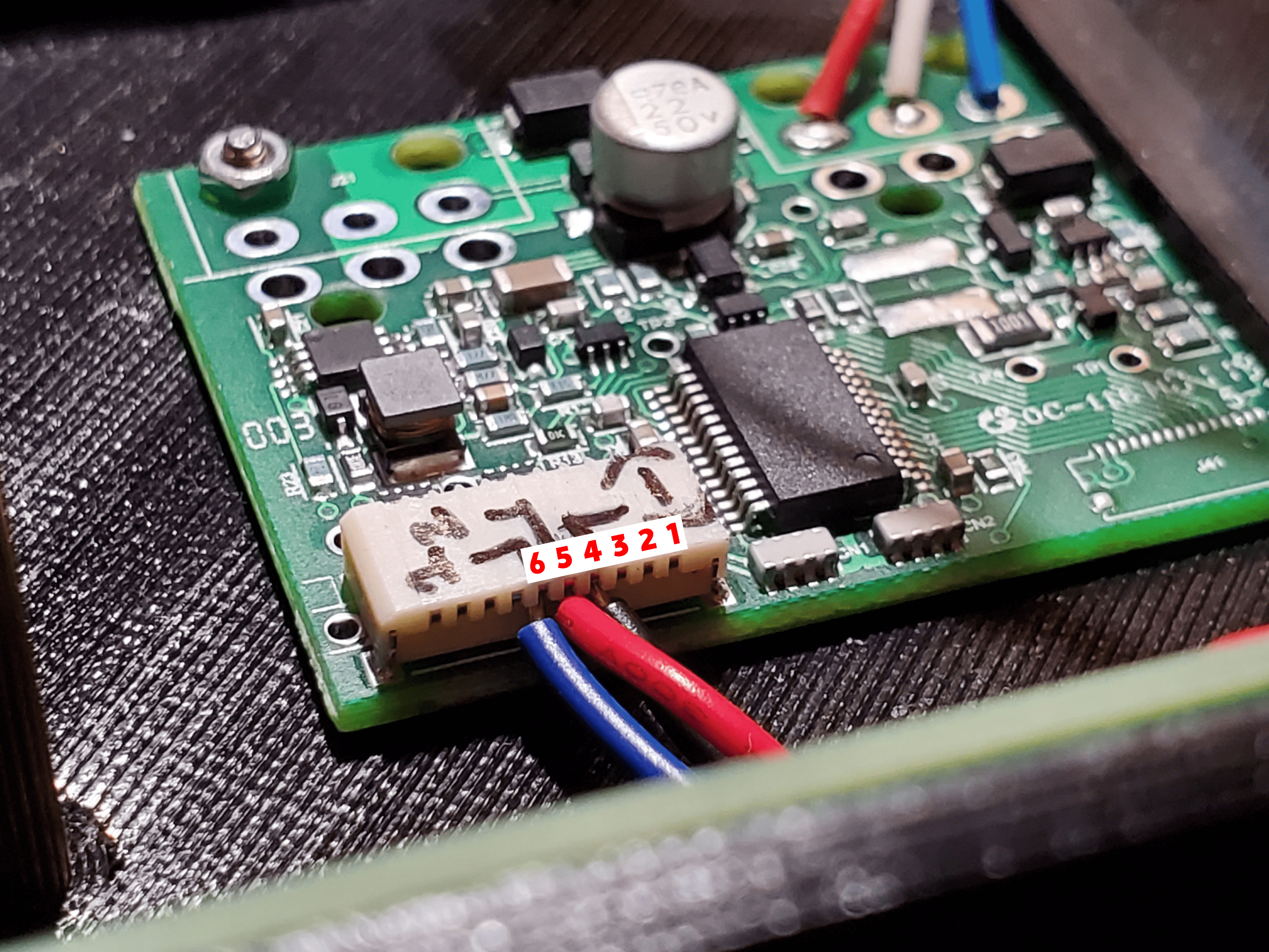
Add desk PCB jumper wires.
Attach three jumper wires into the header of the desk PCB, according to the wiring diagram and the photo below. The insulated portions of mine were about 75mm long (leave extra to plug into the headers). You'll want some length for maneuvering the main PCB into place later.
8
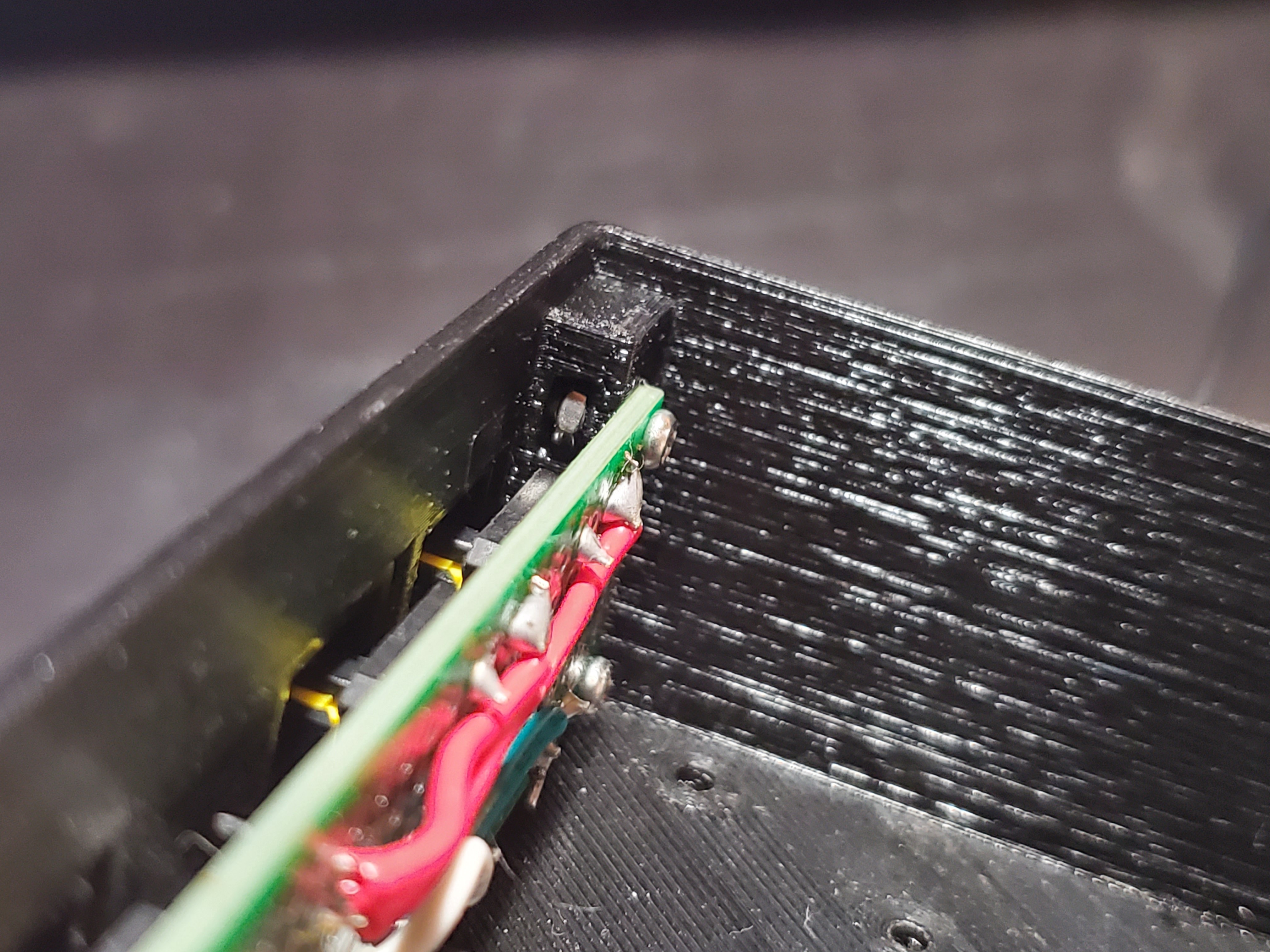
Install desk PCB.
Slip the desk PC under the desk PCB holder, then secure with a 6mm screw and washer through the bottom of the case body, and a nut on top.
9
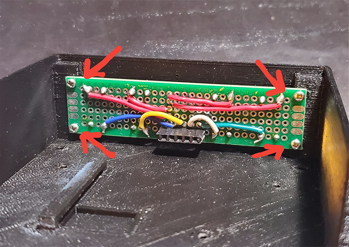
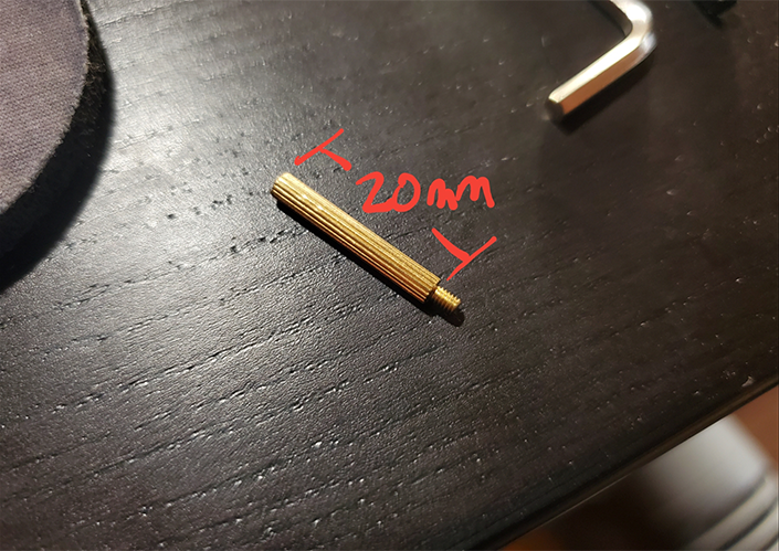
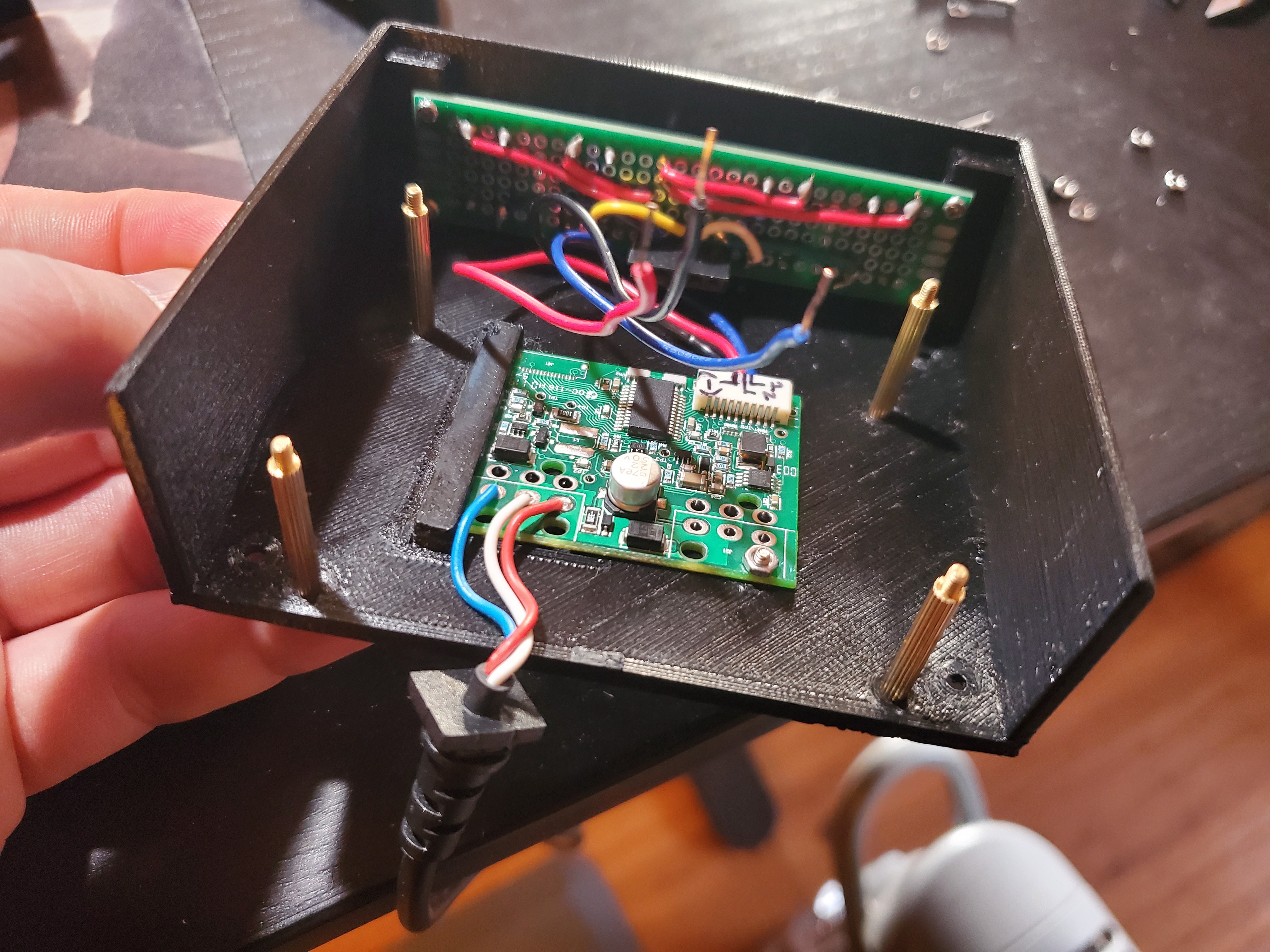
Install standoffs.
Install 20mm standoffs using washers and 8m screws. These will hold the four corners of the main PCB.
10
Add button PCB jumper wires.
Attach five jumper wires to the main PCB header facing the button PCB and bend them into a U. The insulated portions of mine were about 22mm long (again, leave extra to plug into the headers).
 Hardware Unknown


Discussions
Become a Hackaday.io Member
Create an account to leave a comment. Already have an account? Log In.