If I want to be sure that my "invented here" LRU4 is both valid and better than other systems, I must compare them, which means I must also care for the existing systems.
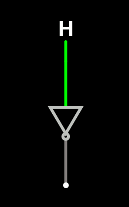
The first obvious choice is the IBM-invented 3-bit tree-LRU (as named and described in the wikipedia page). Which is actually a recursive version of the obvious 1-bit LRU for 2-way associative cache. You can't make simpler than that: it's an inverter!

But for 4 ways, it gets a bit more complex, as quoted in the project description. Fortunately a sort of lookup table is provided:
state | replace      ref to | next state
------+--------      -------+-----------
 00x  |  line_0      line_0 |    11_
 01x  |  line_1      line_1 |    10_
 1x0  |  line_2      line_2 |    0_1
 1x1  |  line_3      line_3 |    0_0
   ('x' means don't care)
   ('_' means unchanged)
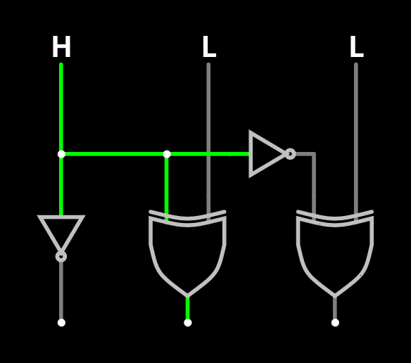
This can be condensed in a few gates:

No wonder this is a favourite method, but is it actually good ? It seems this is out of fashion in the last 20 years.
This is to be compared to the "true LRU", which uses 5 bits in the optimised case.
An MRU mode could be implemented by not updating the bits.
------------------------------------------------------
Another, more modern method (Itanium, SPARC...) is the 4-bit "bit-LRU" with a pretty weird scheme. Quoting Wikipedia:
Bit-PLRU
Bit-PLRU stores one status bit for each cache line. These bits are called MRU-bits. Every access to a line sets its MRU-bit to 1, indicating that the
line was recently used.
At this point, OK I get it, pretty simple and it makes sense: "mark the accessed way as it is used". But then, it is different because after a while, everything will be marked. The method here looks trivial but unheard of:
Whenever the last remaining 0 bit of a set's status bits is
set to 1, all other bits are reset to 0.
WHAT ? you just clear the whole history ???
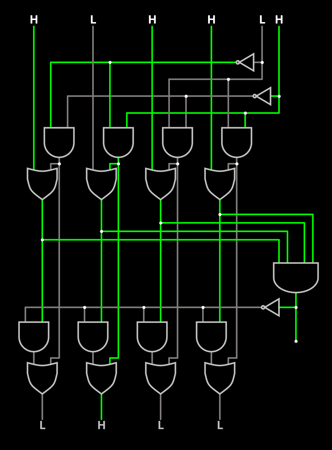
So far this is the corresponding circuit:

At cache misses, the leftmost line whose MRU-bit is 0 is replaced.
There is a priority encoder now? why not a random value to prevent biases ?
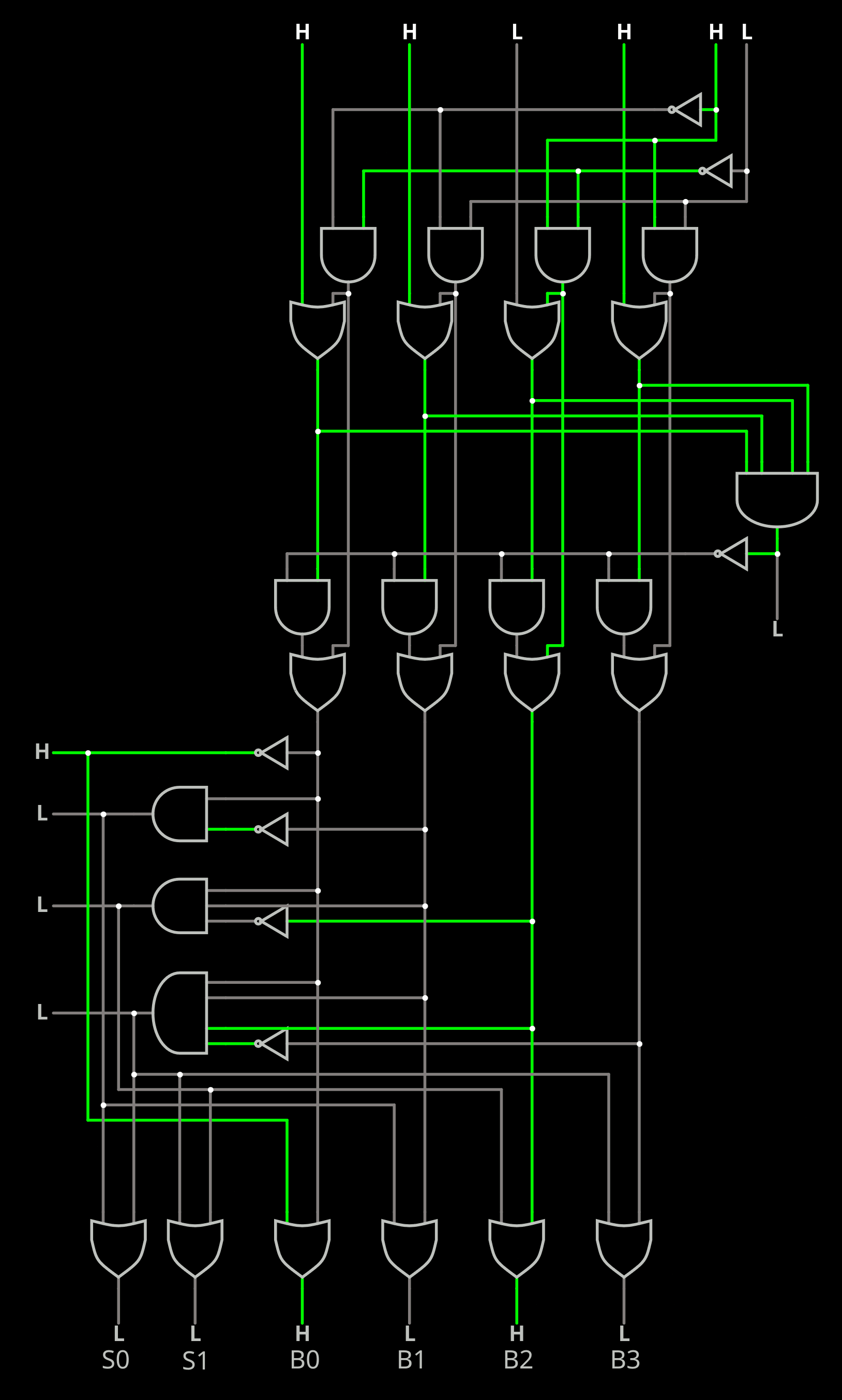
This increases the logic depth, unless a ROM is used. The priority encoder is added below:

This circuit provides both the binary encoded number of the new set to replace, as well as the 4-bit set. The logic depth is 5 here (like the one I designed).
And I'm not sure how to design a MRU mode with it.
Maybe the trick for this system is to send 5 signals to the target line : 4 "set" signals, and one "reset all" signal (overdriven by the one set signal). Set-reset flip-flops take fewer transistors (one half) than DFF gates.
The bias might be how, over time, some lines might get moved toward the "left" and create a sort of natural LRU where the "rightmost" are evicted more often but I have only vague ideas about it and it should be tested as well as documented.
---------------------------------------------------
Update:
I looked at the referenced paper from 2010, where it's called "NRU" (Not Recently Used) and the description is "slightly different" !

So the position of the first candidate rotates, preventing a bias. Is the counter general, or stored with the lines ? The latter would take 2 more bits per line. And a counter is more "concerning" than a PRNG.
...............................................................................................................
And since we're in 2024, power consumption matters, and in this case signal activity (level changes) have a significant importance.
So the rate of changes must be included in the comparisons.
Tree-LRU changes the polarity of 2 signals at every cycle ! (and only uses 8 of the possible 24 permutations).
Bit-LRU might swap 4 bits at once from time to time, only setting one most of the time.
...............................................................................................................
Another detail I seem to have missed is the Hit/Miss behaviour. That means another log about this subject...
 Yann Guidon / YGDES
Discussions
Become a Hackaday.io Member
Create an account to leave a comment. Already have an account? Log In.