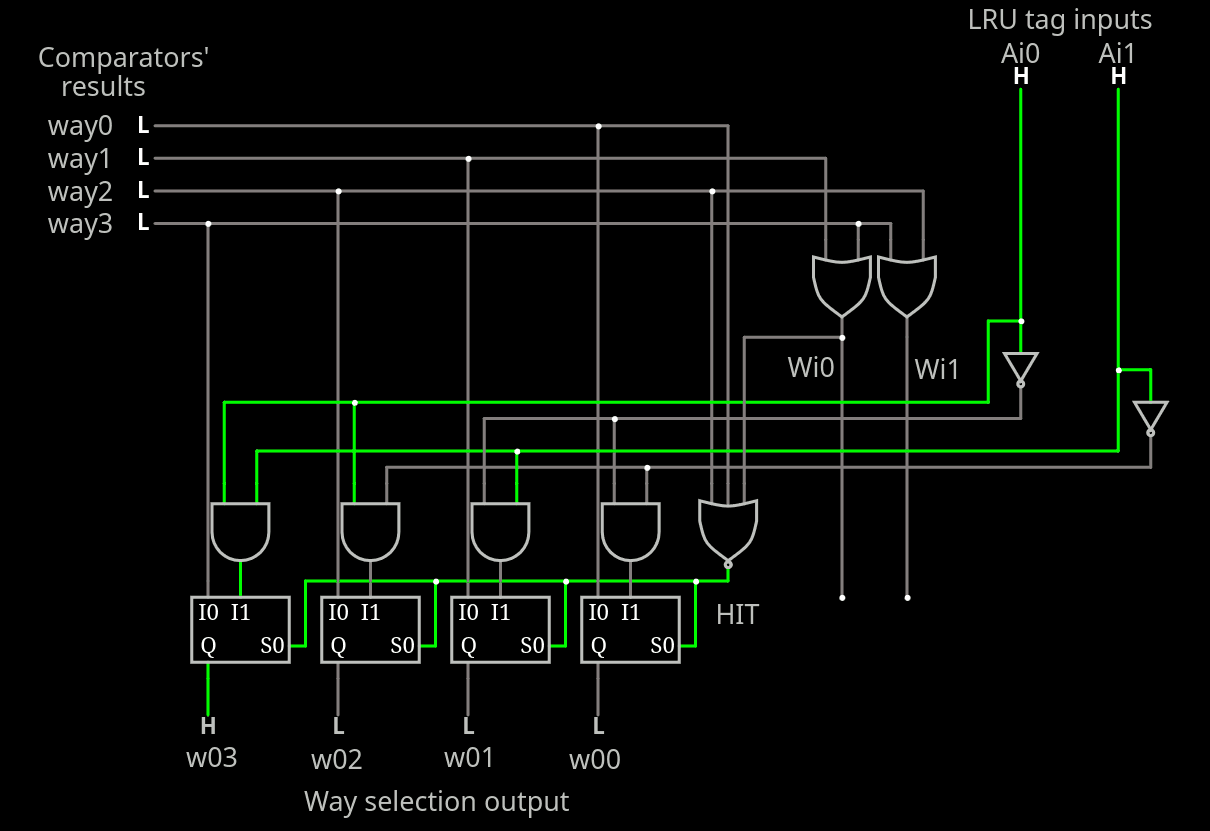
Once again, by writing a log, I realise something I missed before. This new version of myLRU (I decided to give it a cute little egotistical name) is more complete now.
I take the previous version and add 2 signals :
- a HIT input flag
- a WAY output field
This only adds a few more gates and makes it easier to incorporate into a whole cache system.
The HIT input enables the match/comparators, so spurious invalid inputs don't affect the LRU algorithm. It's only a matter of extending the NOR to 3 inputs.
......
Yeah that was a bit premature. So here I start again from scratch:

....
In this circuit, the matching way is encoded to 2 bits and fed to LRU circuit that works in parallel.
- If there is a hit, the "way selector" output is a copy of the input (no need to change it).
- If there is a miss, the "way selector" output is A decoded.
Meanwhile,
- if MRU is set, LRU will keep A and B as is
- otherwise A<=B and B<=new_B
....
So overall, there are 4 cases:
- A<=A, B<=B when MRU=0 & A!=W & B!=W (hit C or D)
- A<=A, B<=new_B when MRU=0 & B=W (hit B)
- A<=B, B<=new_B when MRU=0 & B!=W (hit A)
- A<=W, B<=A when MRU=1 & HIT=1 & A!=W
Note: A=W and B=W is the error condition so there are only 3 relevant conditions for MRU=0, respectively:
- A!=W & B!=W
- A!=W & B=W
- A=W & B!=W
This updates the previous list such that
- A<=A, B<=B when MRU=0 & A!=W & B!=W (hit C or D) or MRU=0 and A=W (hit A)
- A<=A, B<=new_B when MRU=0 & A!=W & B=W (hit B)
- A<=B, B<=new_B when MRU=0 & A=W & B!=W (hit A)
- A<=W, B<=A when MRU=1 & HIT=1 & A!=W (hit B, C or D)
.
.
The effect of HIT is not well defined for the MRU=0.
 Yann Guidon / YGDES
Discussions
Become a Hackaday.io Member
Create an account to leave a comment. Already have an account? Log In.