 Sina Roughani
I'm starting to hate ST for using this package. Sure, the logic inputs separate from the power pins is a nice touch, but using 0.5mm spacing was terrible. In a legged package, the bending and deformation of the legs through rework or drops means they have a higher propensity to short together. If it were 0.5mm spacing in a QFN or DFN package, they could avoid this. It should have been 0.65mm though. Why am I complaining about 0.15mm? Well, now that I have professional inspection lighting, here's the results of assembly a few weeks ago.
Some turned out like this
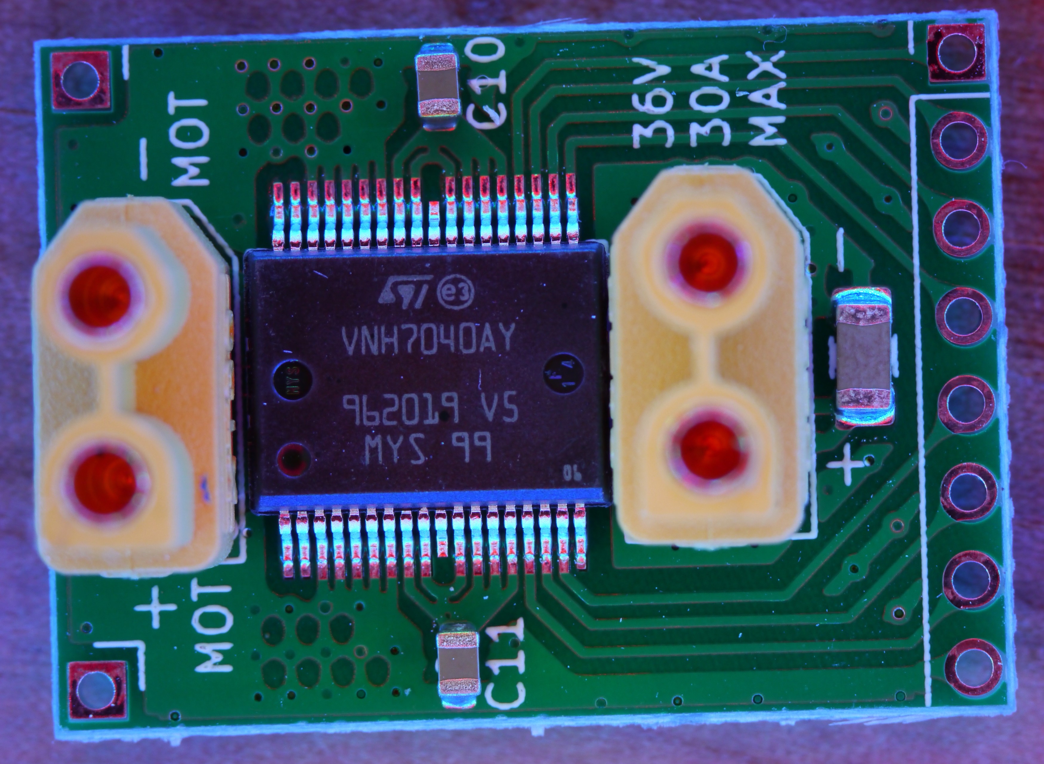
Perfect in every way, just like myself.
And then some turned out like this, actual garbage like myself.
The misalignment couldn't be corrected even after rework.
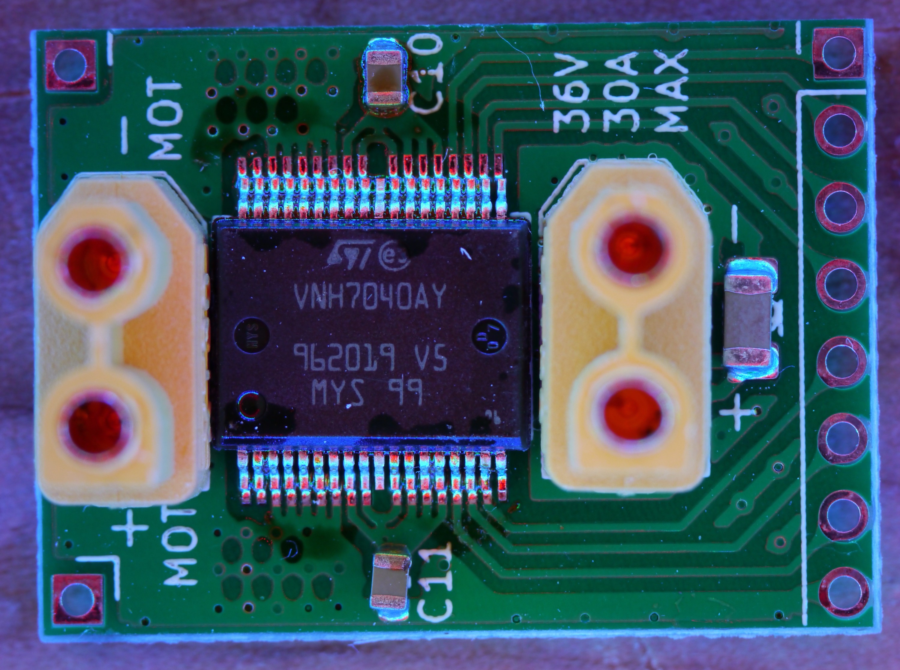
Sure, a swim in the isopropyl bath can clean the flux off, but how do you realign a 0.2mm spacing which has been reduced to 0.1mm? The IPC standards which I don't generally agree with say this is now good for about 10V, and I'd agree with that. But, I'll run it higher because it's not going in a plane, train, or automobile.
Let's take a dip

And after their little bath, they just vibing.
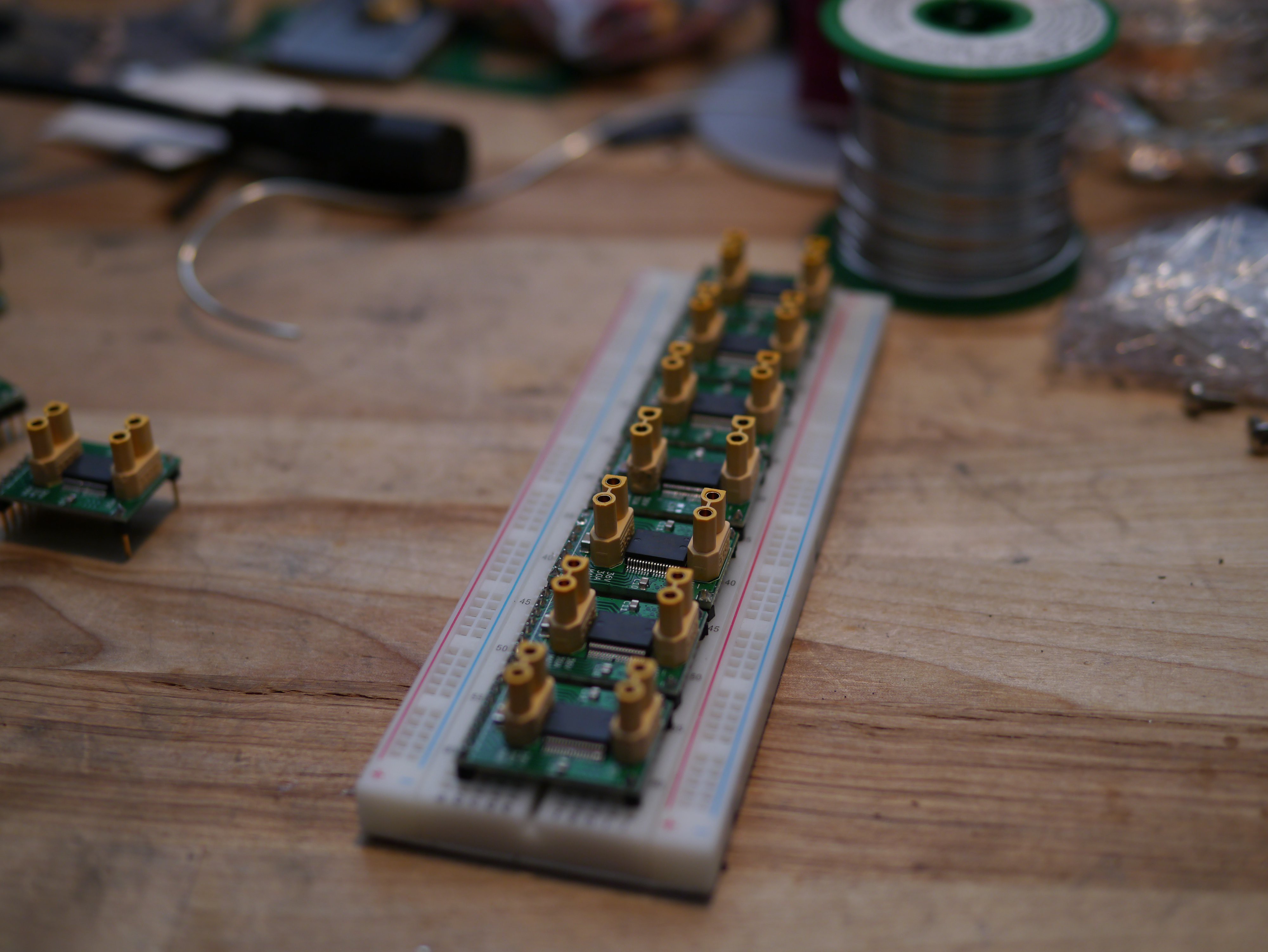
I did an electrical test and surprisingly, none had short circuits.
I'm not willing to trust $10k robots to these though, so I'm going to bin them and put the best in my PUMA robot.
Here's the "Hello Whirl" for the drivers.
Discussions
Become a Hackaday.io Member
Create an account to leave a comment. Already have an account? Log In.