 Pavel Semenov
Synopsis
In my head quite often there are ideas that I would like to implement, they are both in the field of hardware and in the field of software. Often they remain unstarted because someone has already implemented them.
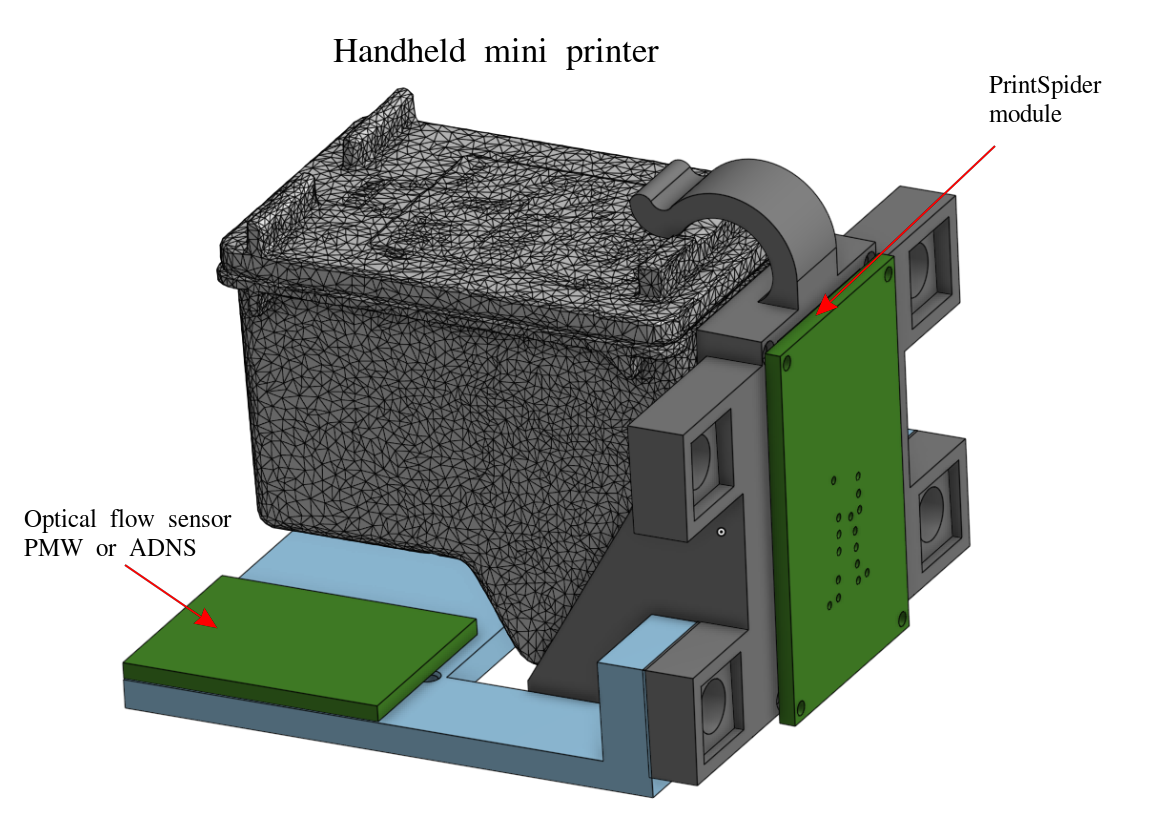
Once again I have a new idea - a project of a handheld printer which would consist of a color printer cartridge and optical flow sensor (the same which is installed in an optical mouse) in a compact case. My idea was that it would print by moving this whole construction over a sheet of paper. A genius idea, and... it already turned out to be implemented, for example here: PrintCube.
Okay, let this particular idea has already been implemented, but many more interesting things can be done based on printing:
- Make DIY handheld mini printer similar to PrintCube.
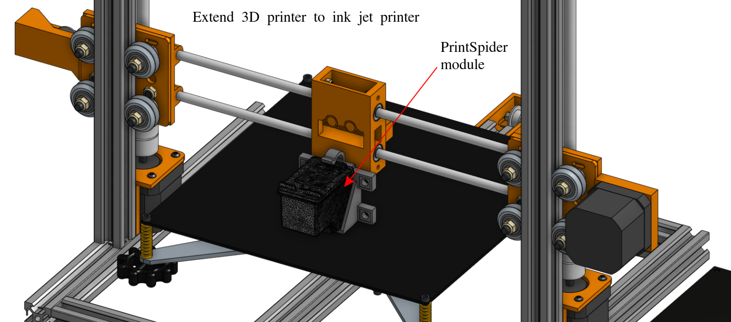
- Make a module for a 3D printer that turns it into a CUPS-based 2D inkjet printer.
- Make a printer that prints with edible ink on cookies, cakes, coffee cups, or whatever else you eat.
- Make a printer that drives on the surface and prints on it. Looks like there were attempts (here: Pill Printer or here: The Mini Mobile Robotic Printer) - nothing came out, but that doesn't mean it's not possible.
Even though these ideas are not new, making something out of it would still be an interesting adventure for a new experience. At first glance the task did not seem too difficult: I would take ready-made modules, which are on the market, put everything in one box and code it. Three easy steps!
Let's see what ready-made solutions for makers on the subject of printing already exist:
- Ink Shield GitHub - Open source solution. Not color. No longer available for purchase.
- Controlling an HP6602 printhead - Open source solution. Not in color. Can't buy an off-the-shelf solution as a module.
- MagicPaintBrush - Open source solution. Color!!! Can't buy an out-of-the-box solution as a module.
- Ytec3D Forum - Lots of information on reverse engineering various cartridges.
All are not in color. Can't buy an off-the-shelf solution as a module.
The list could go on and on, but they all have one thing in common: at the moment, there are no ready-made modules for controlling a color printer cartridge. There is not even a monochrome print module that you could buy and use out of the box.
So this project was born.
Project goal
This project is an attempt to make a compact modular control unit for color/black print cartridges of an HP printer using a microcontroller.
It is based on the already tested in the MagicPaintBrush project by Sprite_tm's solution. The final result of the project: the realization of a working iron prototype in the form of a surface mount board, a 3D printer printable mount, and control software.
Cartridge pinout
Most of the description of the cartridge is taken from here and details of its reverse engineering can be read there. Here is a small part required to implement this project.
The picture shows the pinout of the inputs:
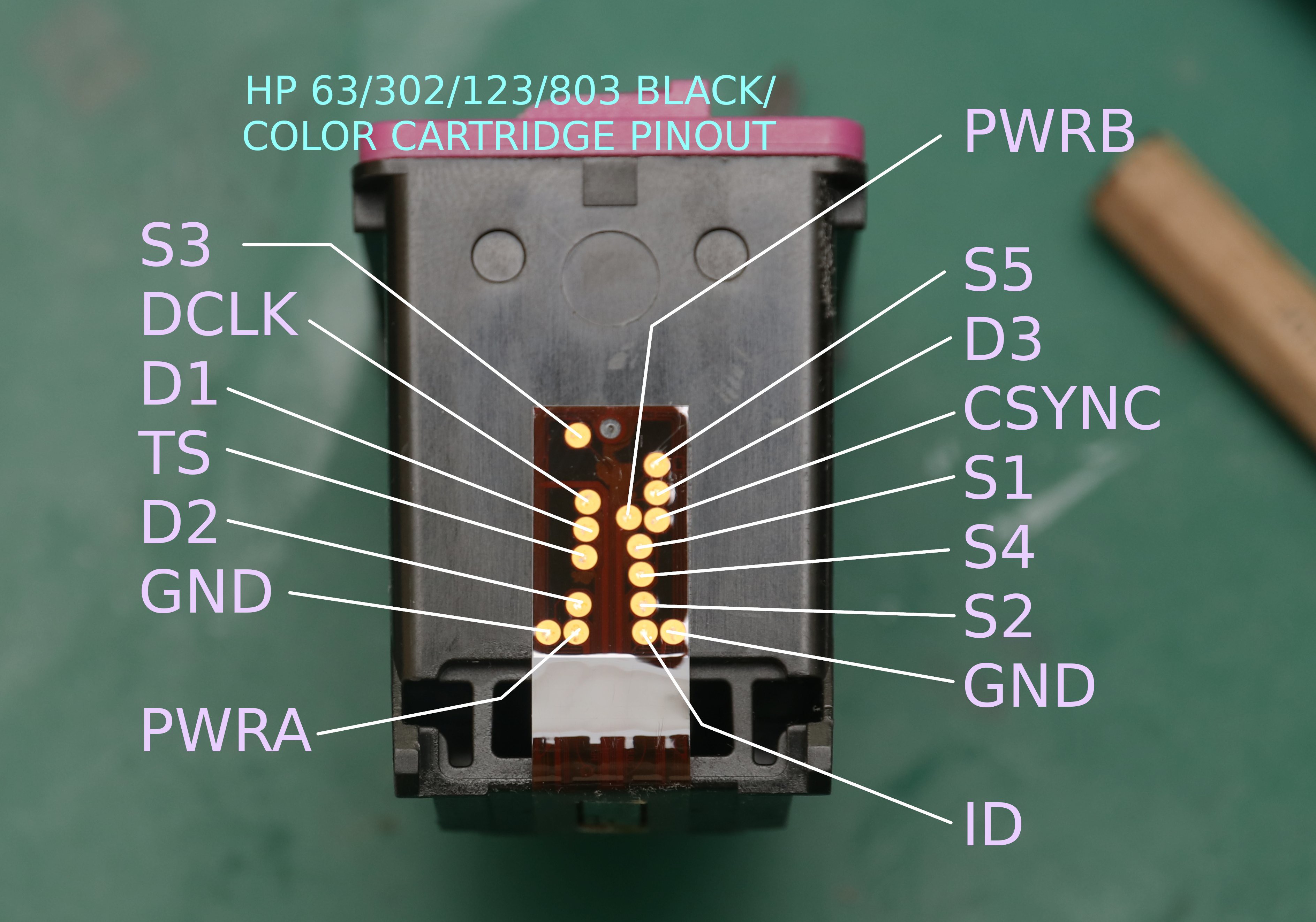
| Label | Description | Voltage level |
| S3 | Clock line. | 16V |
| DCLK | Clock line. | 16V |
| D1 | Data line for the yellow color. | 9V |
| TS | ??? | ??? |
| D2 | Data line for the magenta color. | 9V |
| GND | Ground. | |
| PWRA - F3 | Print trigger line. | 16V |
| PWRB - F5 | Print trigger line. | 16V |
| S5 | Clock line. | 16V |
| D3 | Data line for the color cayan. | 9V |
| CSYNC | Data group switching line. | 9V |
| S1 | Clock line. | 16V |
| S4 | Clock line. | 16V |
| S2 | Clock line. | 16V |
| ID | ??? | ??? |
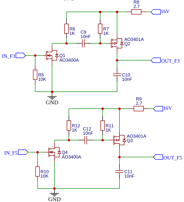
To protect against burning out the nozzles in the cartridge it is necessary to limit the signal time on lines PWRA-F3(hereinafter F3) and PWRB-F5(hereinafter F5) to about 4-10 µs. Failure to do so may cause the nozzle heating resistors to malfunction.
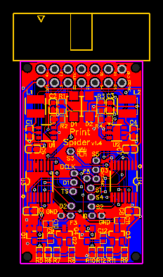
Description of the designed PCB
The board is a converter of 5V input signal levels from the controller to the control signal levels of the cartridge.
Almost all of the circuit solutions were taken from the MagicPaintBrush project.
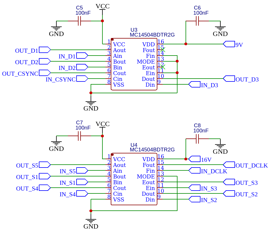
Circuit diagram:
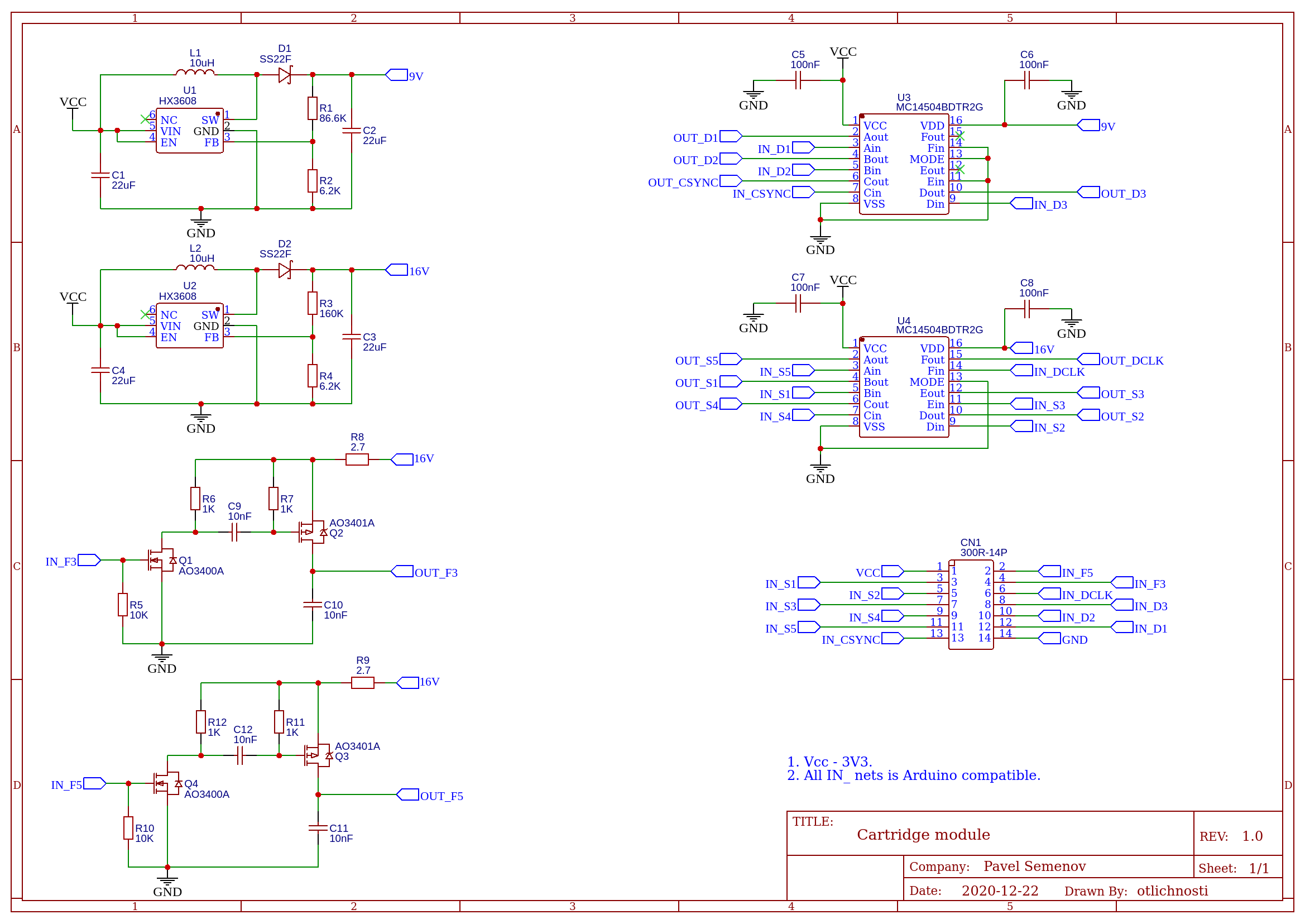
Three blocks can be distinguished here:
1. Block of input voltage conversion from 5V to 9V and 16V.
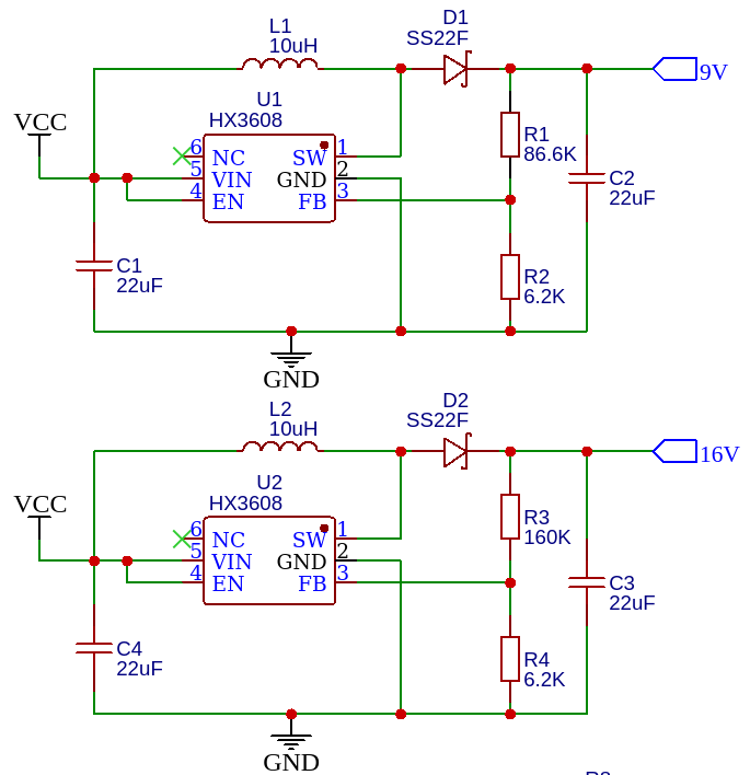
2. The level shifter block of the control signals from 5V levels to the corresponding 9V and 16V levels.
3. Protection unit for print trigger lines with a pulse duration limitation of 10µs.
Note: This part does not seem to work as well as expected, either with or without cartridge connected. See Progress Update 2022-01-12.
The board layout for these schemes is also presented as a Gerber file in the project's file list.
Bill of materials:
| Name | Designator | Footprint | Quantity | Manufacturer Part | Manufacturer |
| 22uF | C1, C2, C3, C4 | C0603 | 4 | C0603X5R226M100NT | SANYEAR |
| 100nF | C5, C6, C7, C8 | C0603 | 4 | CC0603KRX7R9BB104 | YAGEO |
| 10nF | C9, C10, C11, C12 | C0402 | 4 | CL05B103KB5NNNC | SAMSUNG |
| 300R-14P | CN1 | IDC-TH_14P-P2.54_300R-14P | 1 | 300R-14P | Ckmtw |
| SS22F | D1, D2 | SMAF | 2 | SS22F | SK |
| 10uH | L1, L2 | IND-SMD_L3.0-W3.0 | 2 | VLS3012HBX-100M | TDK |
| AO3400A | Q1, Q4 | SOT-23 | 2 | AO3400A | Bourne Semicon (Shenzhen) |
| AO3401A | Q2, Q3 | SOT-23-3 | 2 | AO3401A | Bourne Semicon (Shenzhen) |
| 86.6K | R1 | R0603 | 1 | 0603WAF8662T5E | UniOhm |
| 6.2K | R2, R4 | R0603 | 2 | AECR0603F6K20K9 | ResistorToday |
| 160K | R3 | R0603 | 1 | AECR0603F160KK9 | ResistorToday |
| 10K | R5, R10 | R0402 | 2 | TC0225B1002TCE | Uniroyal Elec |
| 1K | R6, R7, R11, R12 | R0402 | 4 | 0402WGF1001TCE | UniOhm |
| 2.7 | R8, R9 | R0402 | 2 | 0402WGF270KTCE | Uniroyal Elec |
| HX3608 | U1, U2 | SOT-23-6 | 2 | HX3608 | hengjiaxing |
| MC14504BDTR2G | U3, U4 | TSSOP-16 | 2 | MC14504BDTR2G | ON Semicon |
Mount design
To create the mount for the printer cartridge on the PCB the exact size of the cartridge was needed, so the cartridge itself was scanned with a professional 3D scanner. The scan can be found in the project files. This scan was then used as the basis for building a model of the mount around it in a CAD application.
I originally chose FreeCAD to design the model and the first and second versions were made with it. After implementing the second version of the mount, I changed FreeCAD to the online service onshape.com as being more convenient, less glitchy, and free for open source projects.
The CAD model of the current version can be found here. The model’s STL file for 3D printing is in the project files.
Drawing with dimensions:
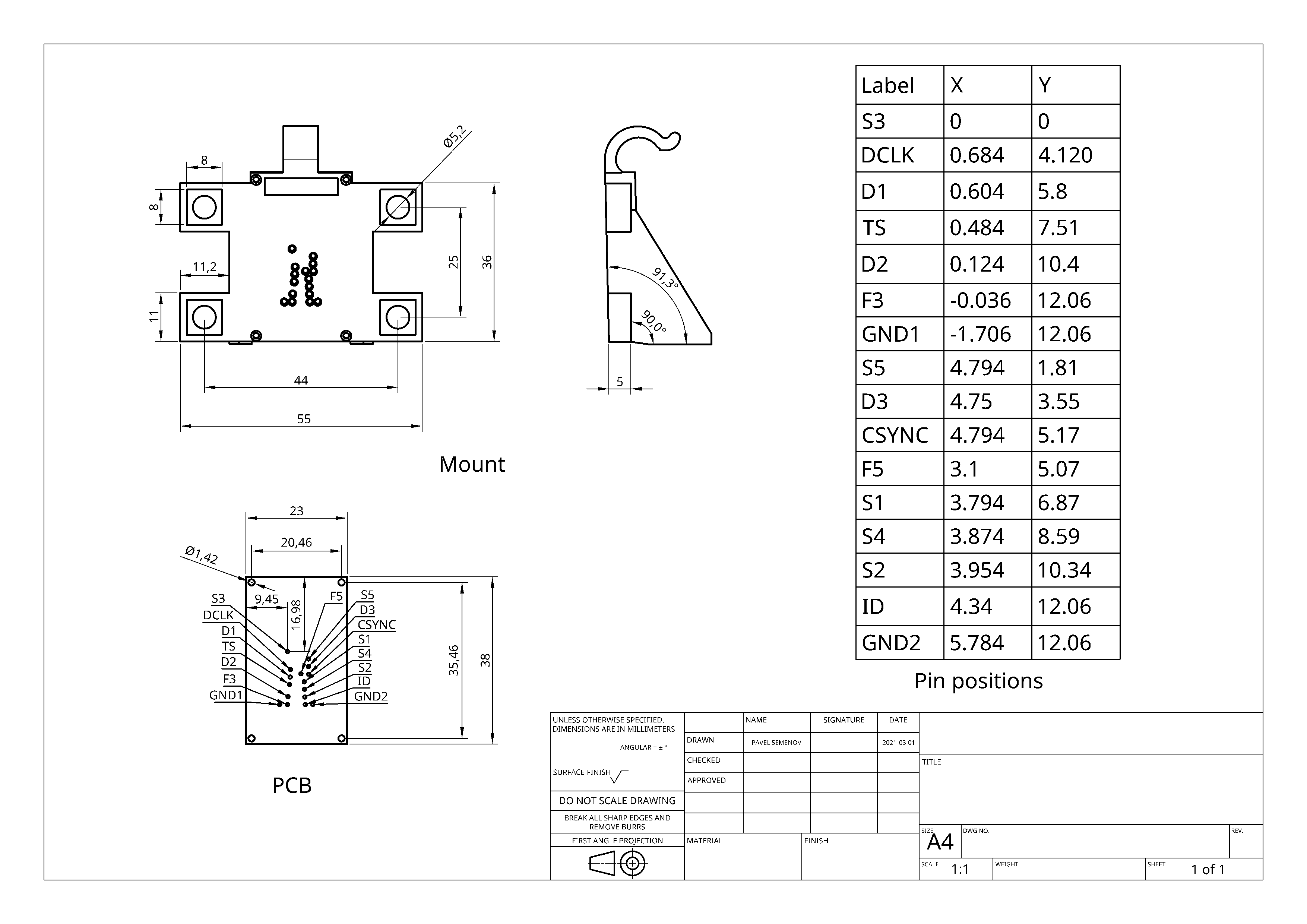
Here you can see that the side where the PCB is mounted is tilted at an angle of 91.3 degrees. This is due to the inclination of the contact area on the cartridge relative to the surface on which the nozzles are located. This ensures the parallelism of the cartridge contact area and the PCB.
I had to tilt also the outer surface of the "wings" where there are holes for bolts that can fasten the whole assembly anywhere.
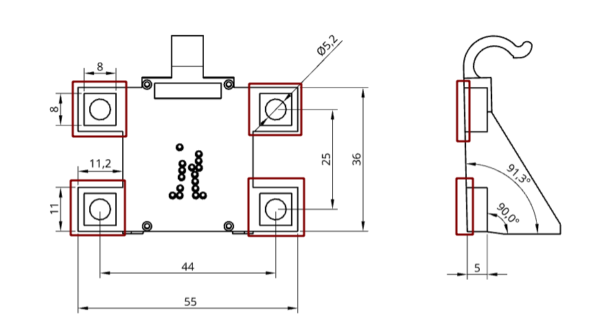
They were originally at 90 degrees to the base of the mount. This part had to be tilted because the service where I printed this part could not provide the required print quality without this tilt, since the ears were protruding and required printing supports. I assume this was due to the lack of professionalism of the service itself.
Licensing
Software source code: Apache License, Version 2.0.
Hardware: CERN Open Hardware License Version 2 - Weakly Reciprocal.
3D models: Creative Commons Attribution-ShareAlike 4.0.