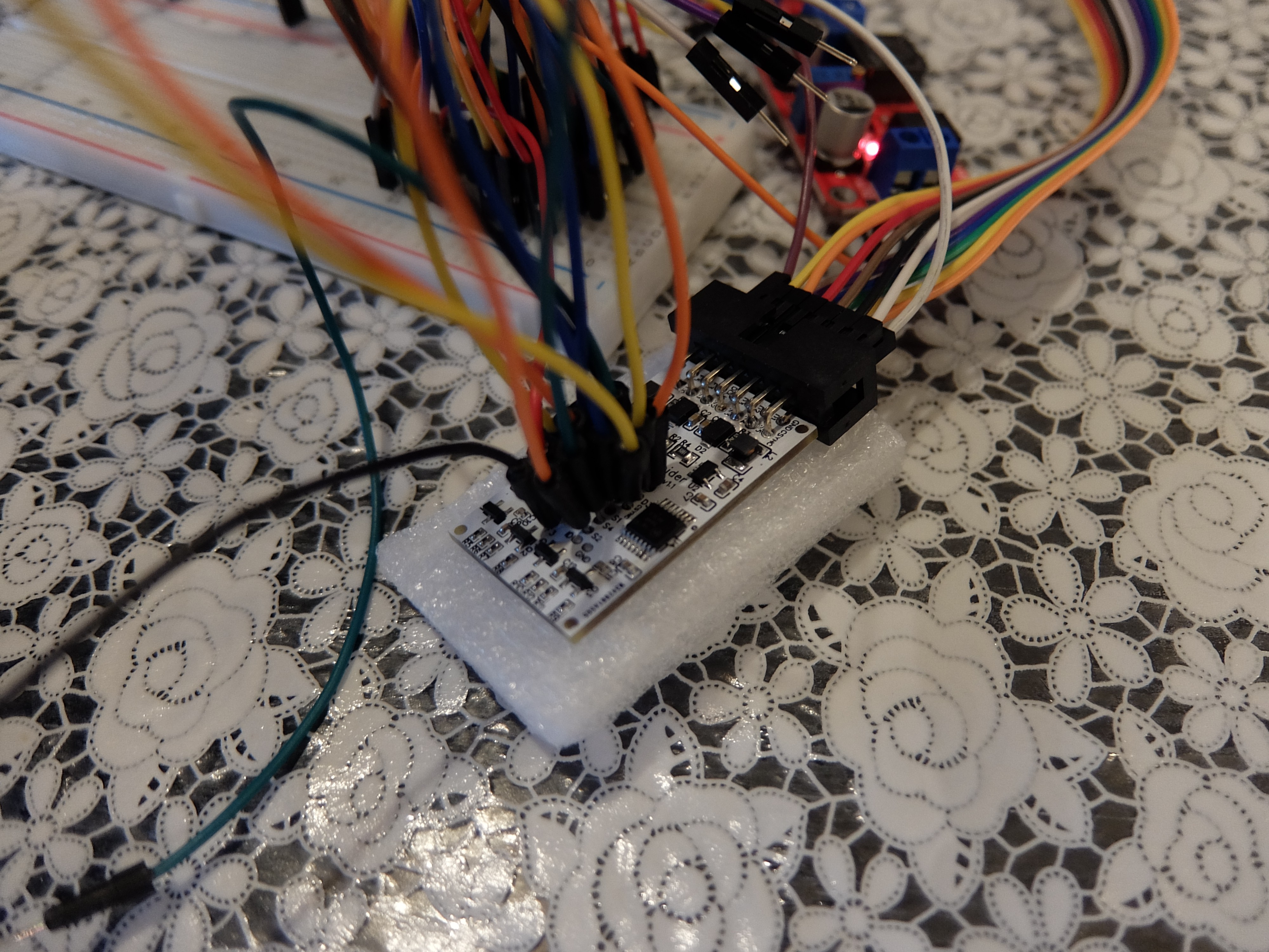
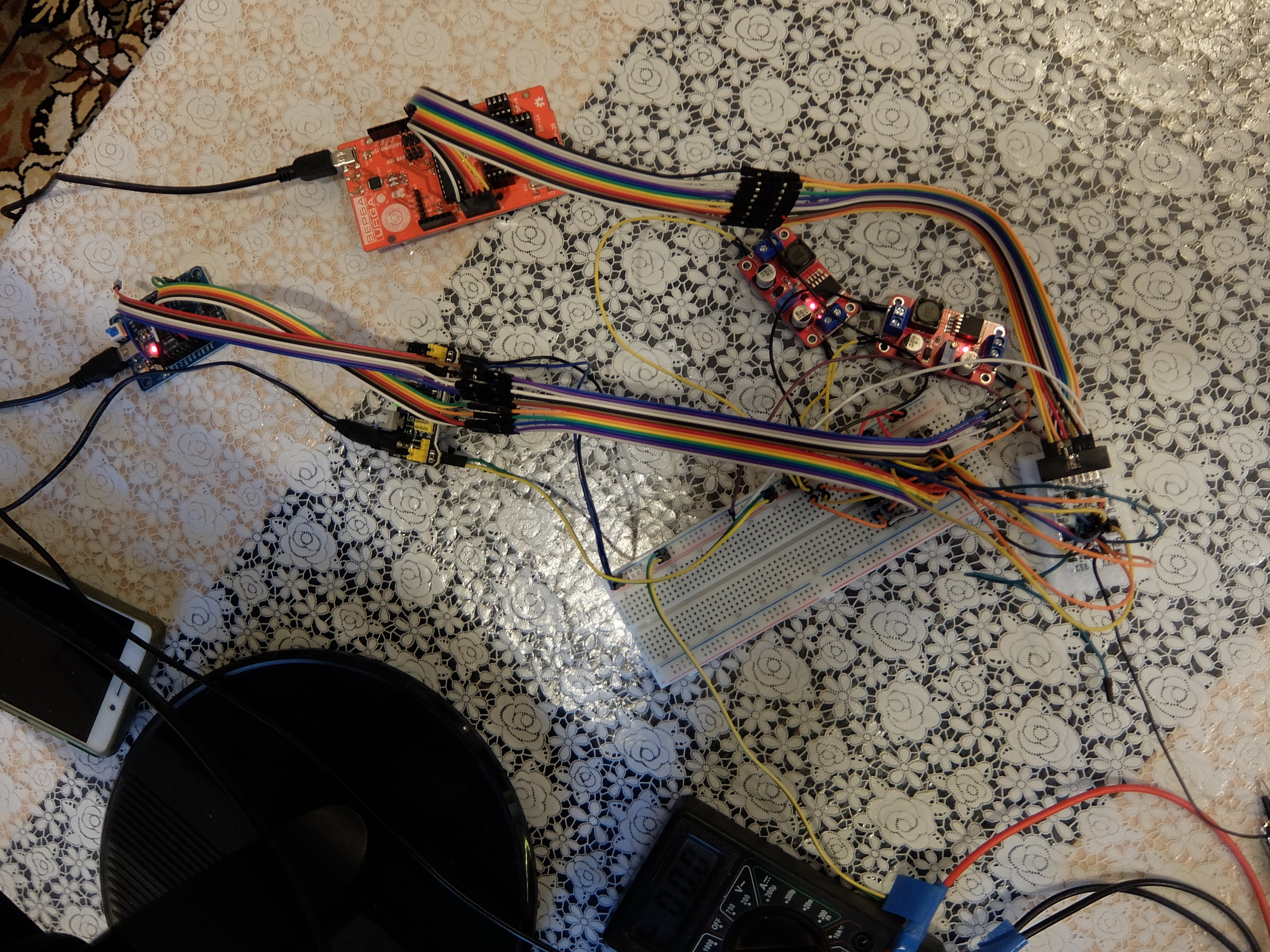
I have not been written for a while but debugging of the assembled solution is in progress. Slowly but it's moving forward.

After tests of each component independently, it seems that all parts work correctly:
- The software produces correct signal sequences.
- The PCB converts levels correctly.

But when I put it all together and tested it with a real cartridge, nothing happened. The cartridge does not print... unfortunately...
I have switched the environment from Arduino to ESP32, have been implementing some debug code for it, have been written a monkey generator tool that adds some adjustments to the base signal sequences... Minor sequence adjustments have not yielded any results... unfortunately...
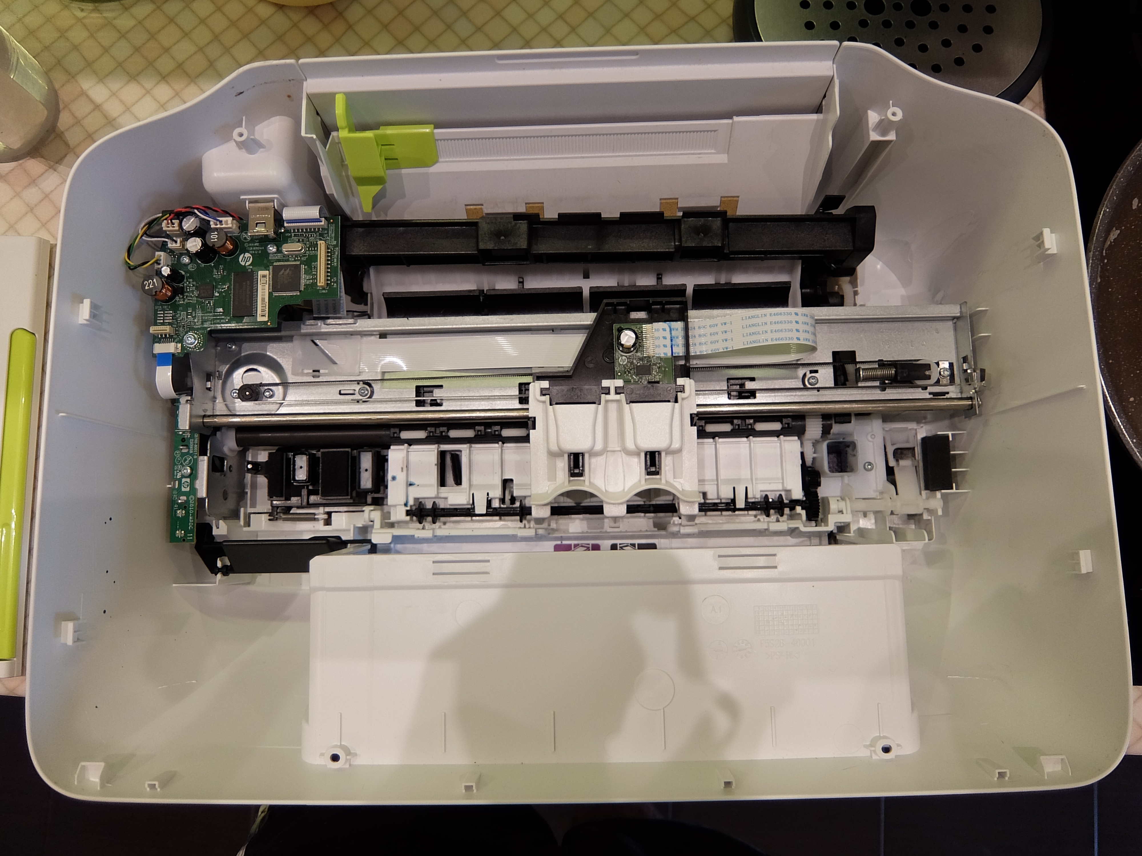
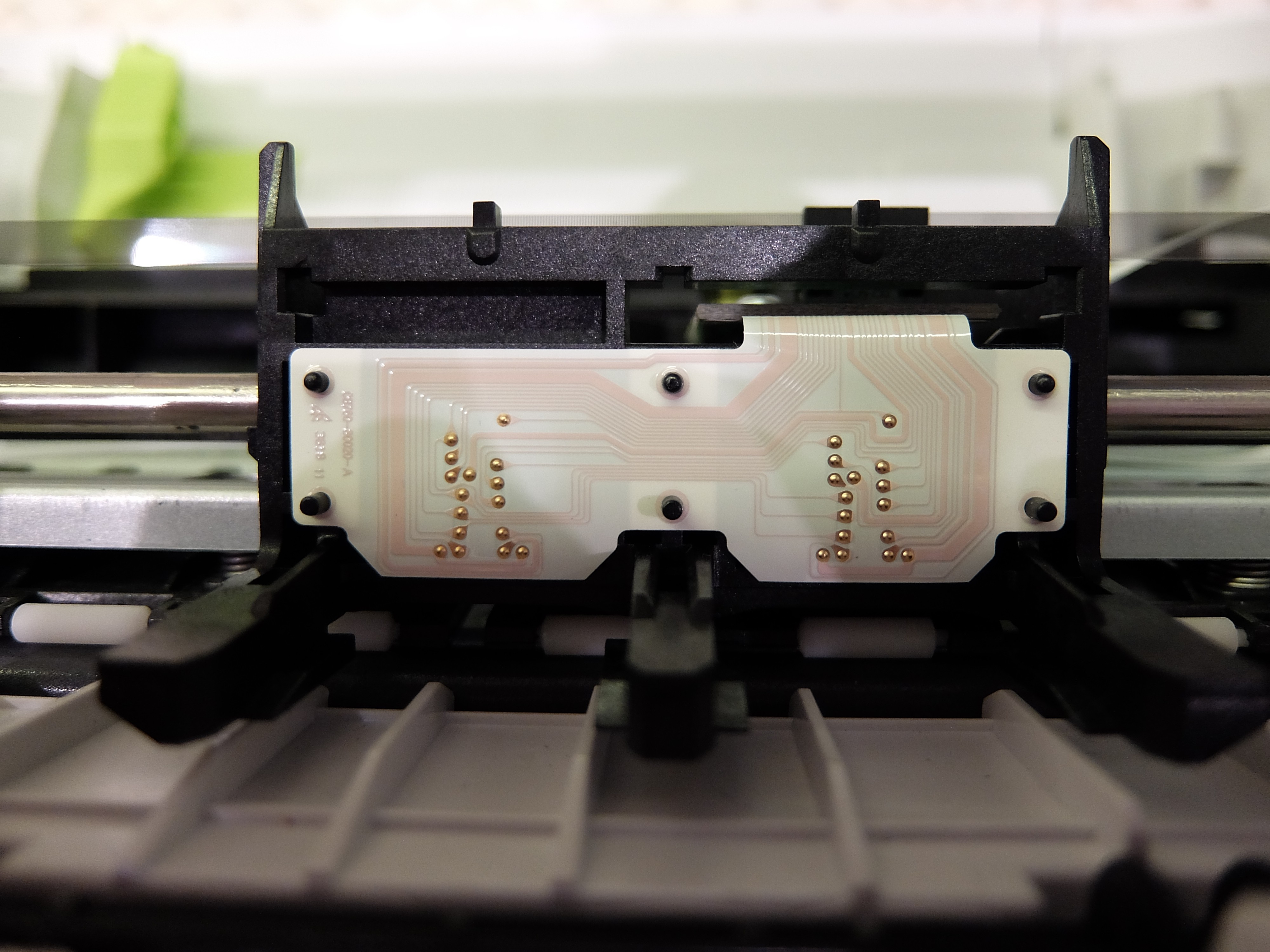
I suggested that this might be so. So I decided to buy a whole printer, disassemble it and reverse engineer target signals to compare what is the difference between my implementation of sequences and the original one.

The contacts which are going to the color and black print cartridge would be brought out as two IDC ports.

Then all data will be logged with the oscilloscope and will be analyzed. All dumps will be presented here.
The journey continues.
 Pavel Semenov
Discussions
Become a Hackaday.io Member
Create an account to leave a comment. Already have an account? Log In.