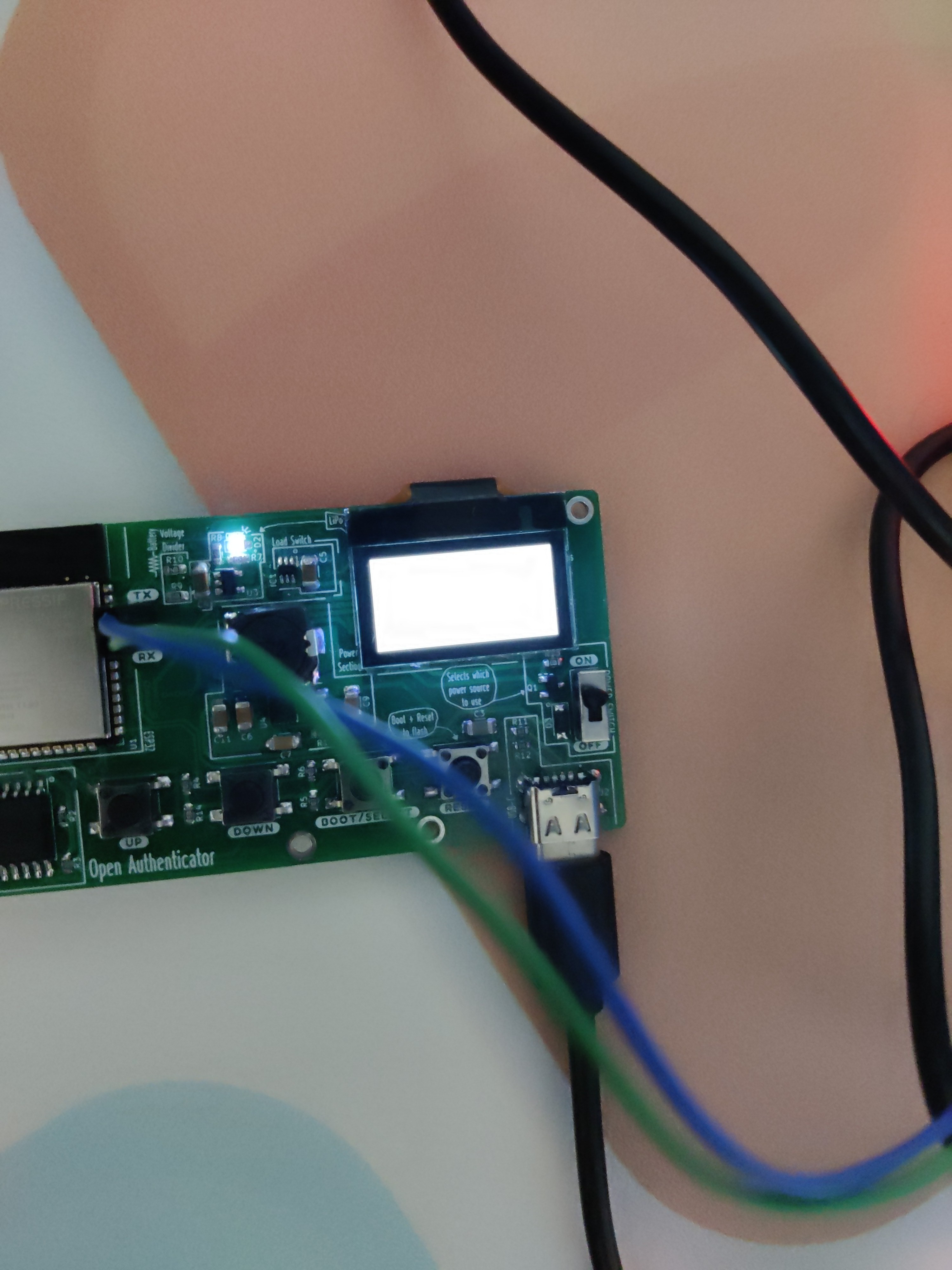
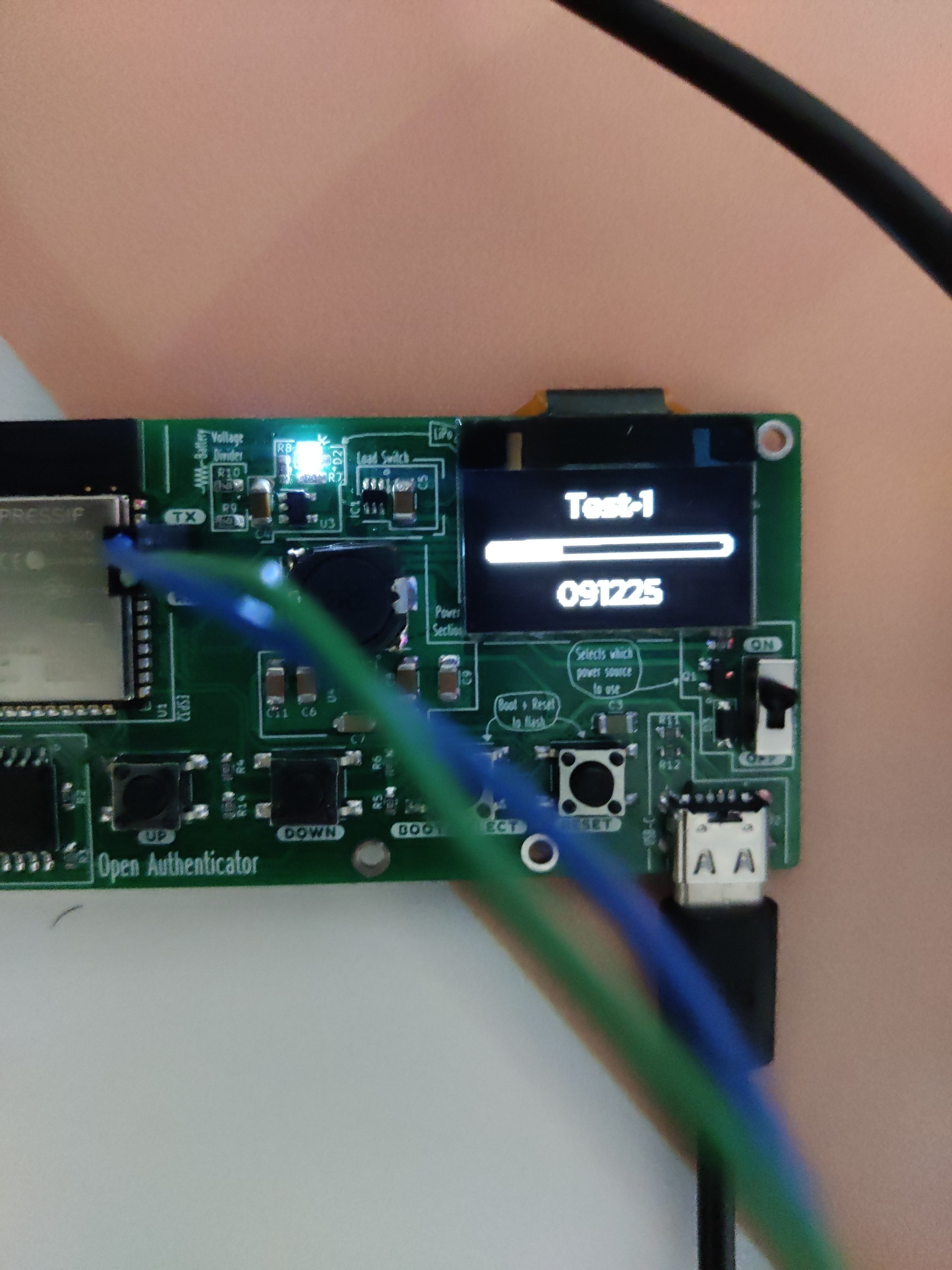
After I received the board, soldered the passive components on it. Checked for any shorts, there weren't any. Connected USB and flashed the firmware onto it, and it booted fine, except for one problem. The OLED was all white like this. I was not sure what the issue was.

I rechecked all the solder joints, and it seemed fine. Likewise, I was puzzled as to what went wrong. So, just started fiddling with the reset button and power switch, and then by some random action it started working.

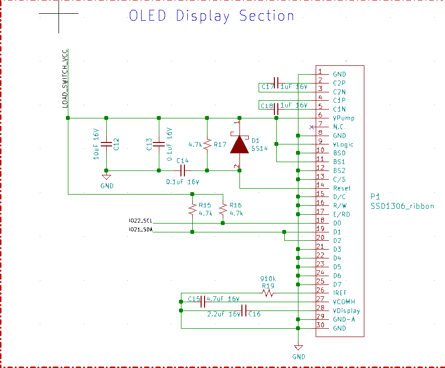
Upon further investigation, I realized that there was some issue with the reset circuit. So, according to the data sheet, we need to hold the RES pin low while on power up to execute the reset on OLED, and then pull it high thereafter.

So the core problem was that the RC Circuit on the reset. The value of capacitor and resistor was too small, so the time required for charging the cap was too small, as a result RES# pin was pulled low for only

The Relevant circuit is C14 and R17, they form an RC circuit. So, after rumbling through the stock I had a dozen 310k resistors, plugged it into the equation.
 Vedant Paranjape
Discussions
Become a Hackaday.io Member
Create an account to leave a comment. Already have an account? Log In.