0%
0%
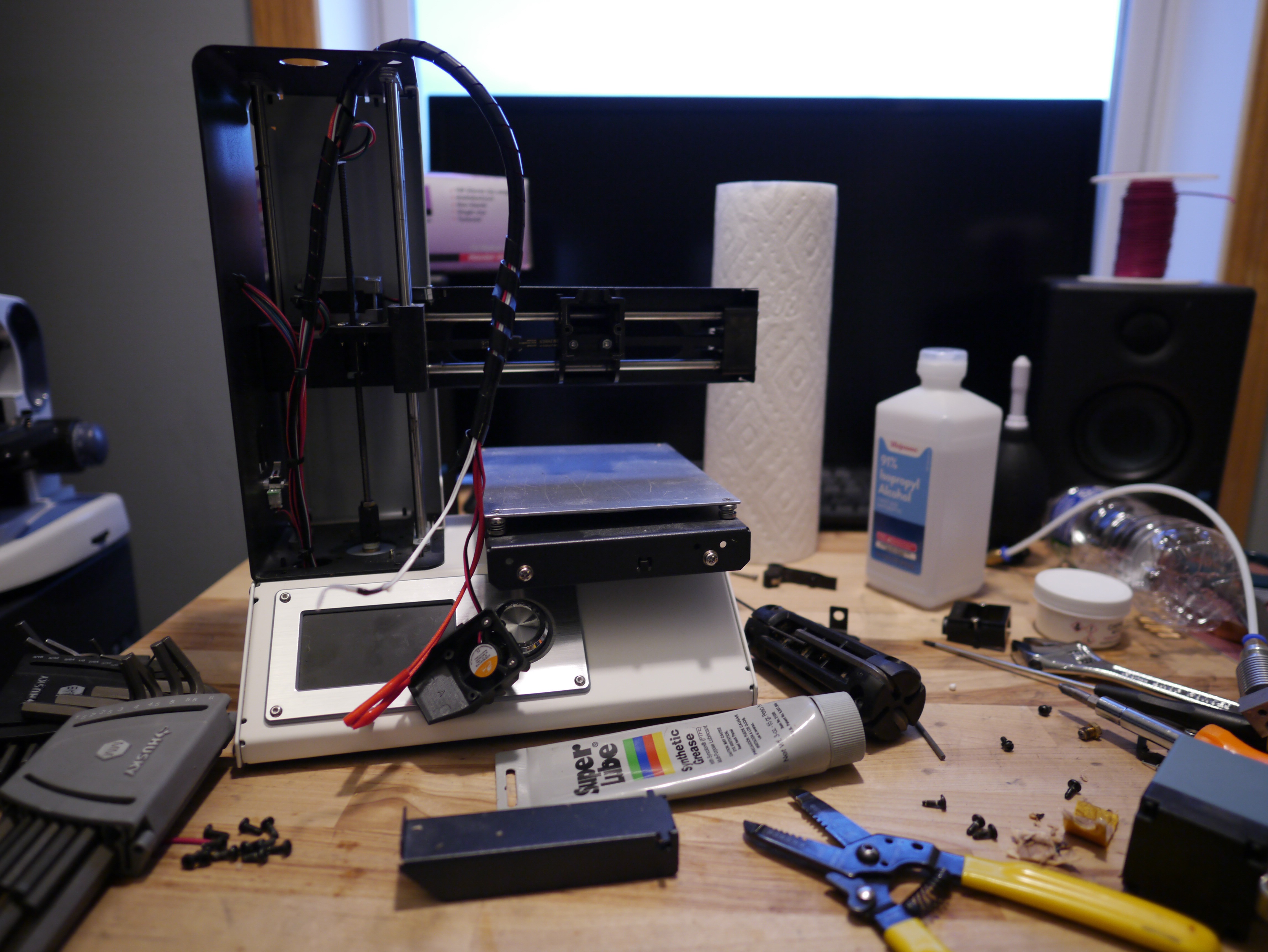
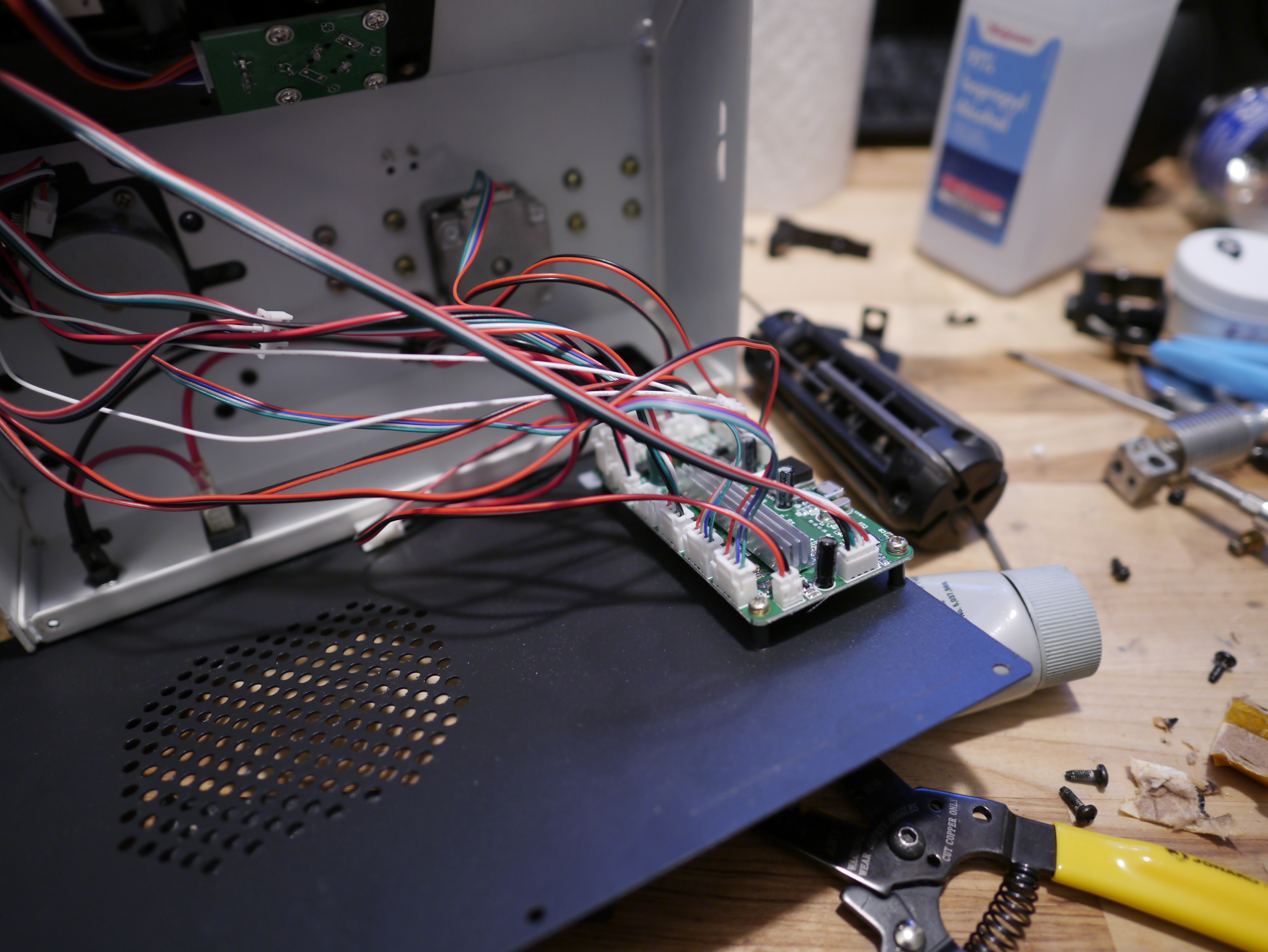
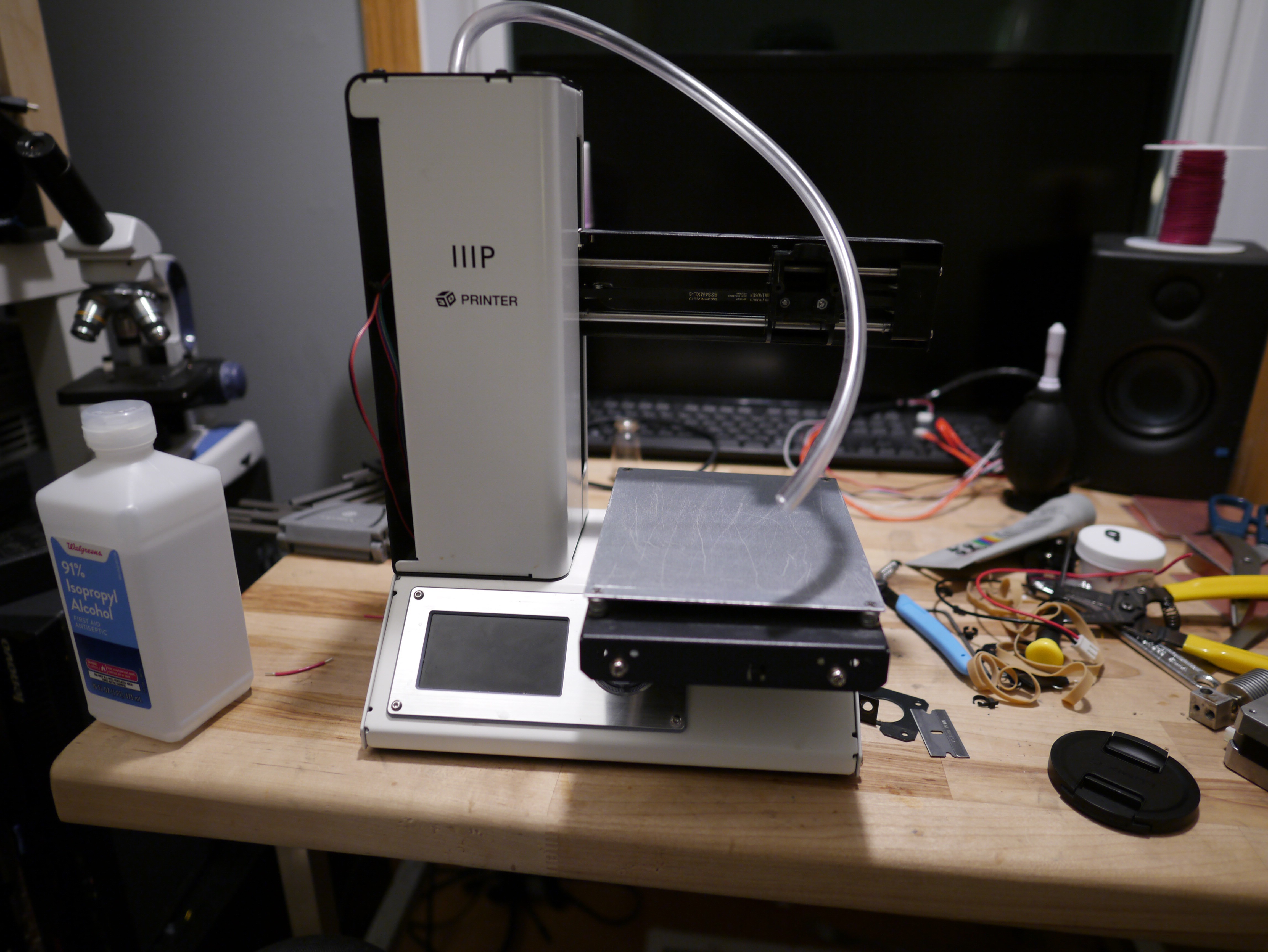
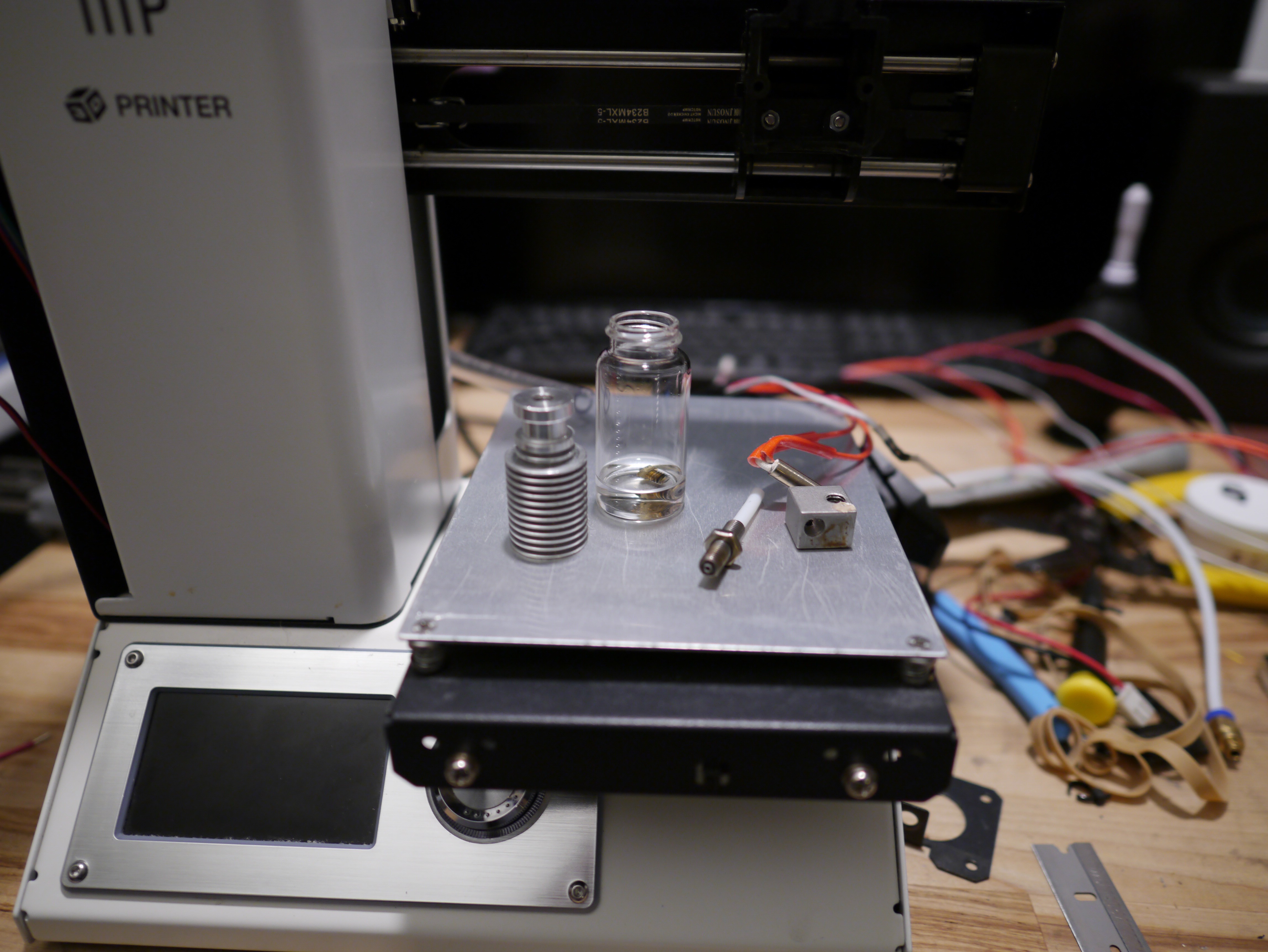
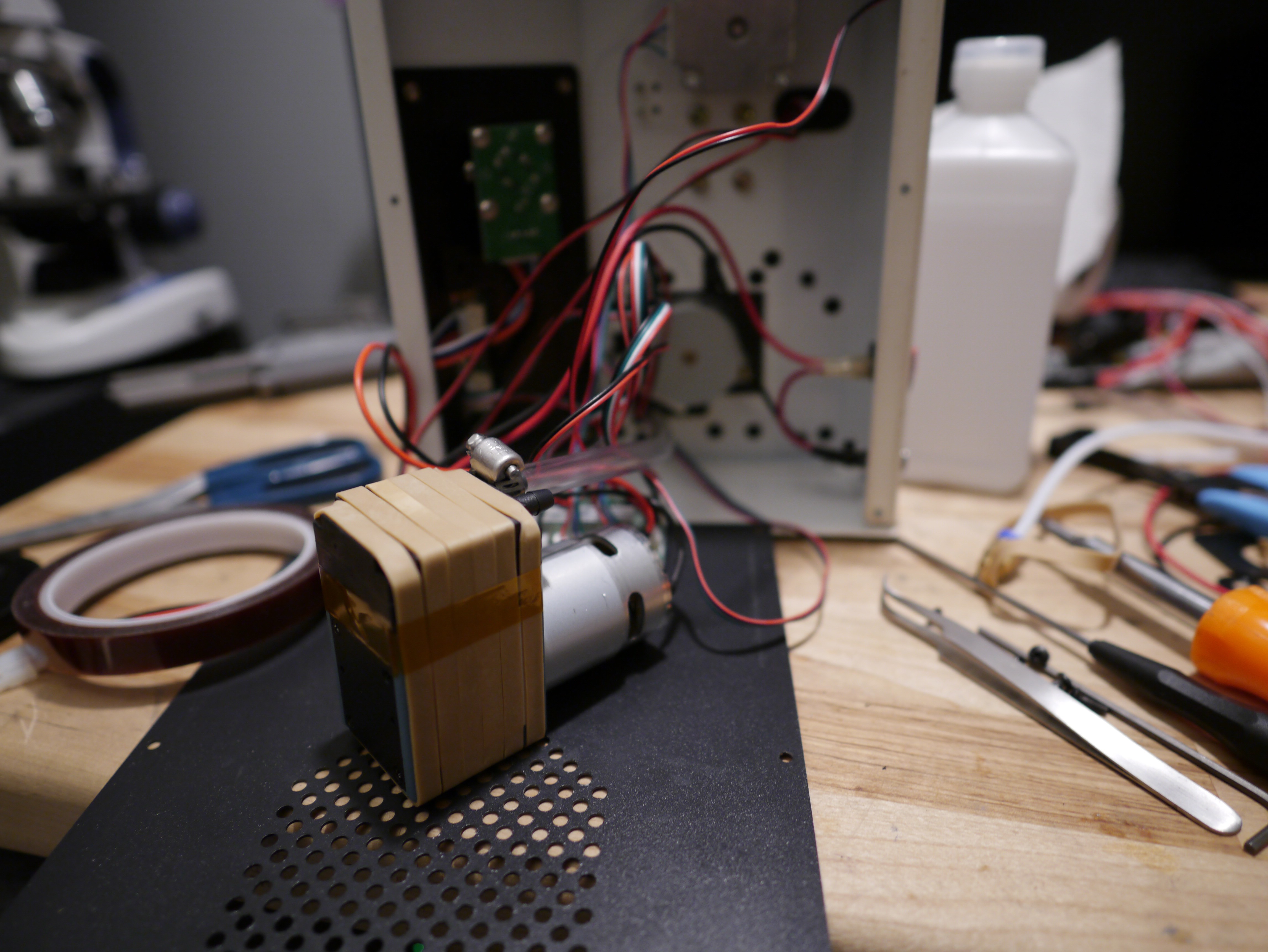
Convert a 3D Printer to a Pick and Place Machine
My Monoprice 3D printer's firmware wouldn't print anything. Then I needed to place a WLCSP chip, and you won't believe what happened next!
 Sina Roughani
Become a Hackaday.io member
Already have an account? Log in.
Just one more thing
To make the experience fit your profile, pick a username and tell us what interests you.
Pick an awesome username
hackaday.io/
Your profile's URL: hackaday.io/username. Max 25 alphanumeric characters.
Pick a few interests
Projects that share your interests
People that share your interests

 Luke Brandon
 E/S Pronk
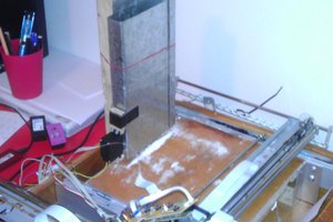
 JLAM
JLAM
Super cool! What does the software side look like?