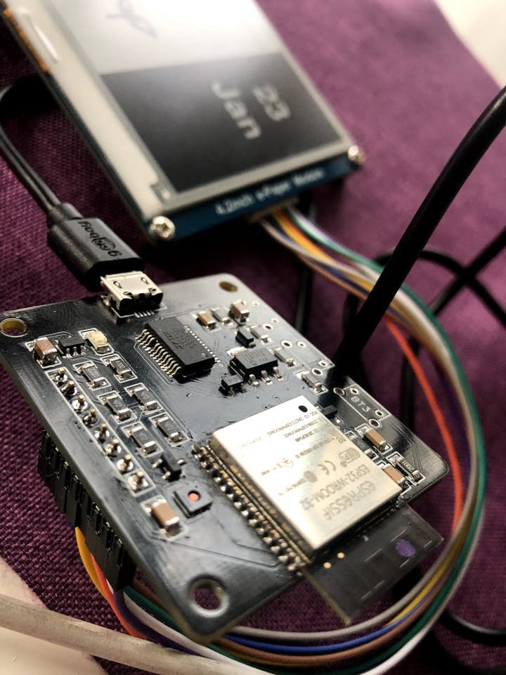
I needed a device that can store the date of a specific event, which I can check later. To be more precise, I needed a device that can store the last date I fed the flowers. The device must be portable and powered by a battery. And because a whole display only for one date is a bit of a waste, I decided to add more features like weather and calendar widgets.
The obvious choice for the display was E-Paper, and for the IC initially, I picked esp8266, but after comparing it with esp32, I had to switch it.
The esp32 has a feature that is very important for this project - esp_sleep_enable_ext1_wakeup. This allows IC to wake with almost any from the GPIO(here a good tutorial https://randomnerdtutorials.com/esp32-external-wake-up-deep-sleep/).

Details
There are many ESP32 development boards, and probably most of them are suitable for this project, but when you have a low-cost PCB prototype manufacturer like PCBWay, I prefer to make my own board. It took just less than a week from ordering to receiving my PCBs
Currently, this device can be flashed directly through a USB, it has a temperature and humidity sensor, LiPo charger, three buttons, and the PCB size is just 50x44mm

The lifecycle of the dashboard is:
- wake from either TIMER or RTC GPIO
- collect data from the sensor via i2c
- optionally read wake source(on from the buttons or time) and write new event date into the EEPROM
- read EEPROM for stored date events
- make API call for weather and calendar widget
- render data to E-Paper via SPI
- set external wake pins
- set wake time for 1 hour
- go to sleep again
About deep sleep
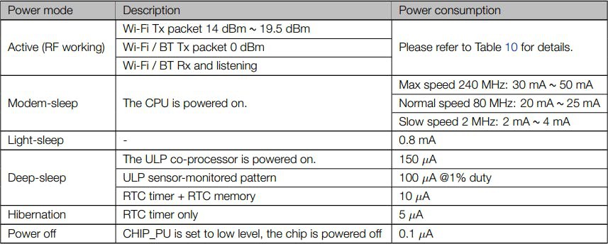
If you put your ESP32 in deep sleep mode, it will reduce the power consumption and your batteries will last longer.
Having your ESP32 in deep sleep mode means cutting with the activities that consume more power while operating, but leave just enough activity to wake up the processor when something interesting happens.
In deep sleep mode neither CPU or Wi-Fi activities take place, but the Ultra Low Power (ULP) co-processor can still be powered on.
While the ESP32 is in deep sleep mode the RTC memory also remains powered on, so we can write a program for the ULP co-processor and store it in the RTC memory to access peripheral devices, internal timers, and internal sensors.
This mode of operation is useful if you need to wake up the main CPU by an external event, timer, or both, while maintaining minimal power consumption.

About wake up
This device is waked up by two sources - either from RTC GPIOs or from TIMER. The first allows us to use multiple pins. You can use two different logic functions:
- Wake up the ESP32 if any of the pins you’ve selected are high;
- Wake up the ESP32 if all the pins you’ve selected are low.
To use this wake up source, you use the following function:
esp_sleep_enable_ext1_wakeup(bitmask, mode)
This function accepts two arguments:
- A bitmask of the GPIO numbers that will cause the wake up;
- Mode: It can be:ESP_EXT1_WAKEUP_ALL_LOW: wake up when all GPIOs go low;ESP_EXT1_WAKEUP_ANY_HIGH: wake up if any of the GPIOs go high.
To get the GPIOs bitmask, follow the next steps:
- Calculate 2^(GPIO_NUMBER) for each pins
- Sum all results
- Convert the sum in hex
In this project I use pin 12, 13 and 14 for wake up, so my bitmask is:
- 2^12 + 2^13 + 2^14 = 28 672
- 28 672 in dec is equal to 0x7000 in hex
Identifying the GPIO used as a wake up source
When you use several pins to wake up the ESP32, it is useful to know which pin caused the wake up. For that, you can use the following function:
esp_sleep_get_ext1_wakeup_status()
This function returns a number of base 2, with the GPIO number as an exponent: 2^(GPIO_NUMBER). So, to get the GPIO in decimal, you need to do the following calculation:
int GPIO_reason = esp_sleep_get_ext1_wakeup_status();Serial.print("GPIO that triggered the wake up: GPIO ");Serial.println((log(GPIO_reason))/log(2), 0);
About the custom board...
Read more » Boris Shabanov


What is the e-paper part? Model, manufacturer.