
From the start this project has focused on variations of a single basic design using 100mm rods. Late last year I experimented with reduced and stretched variations.
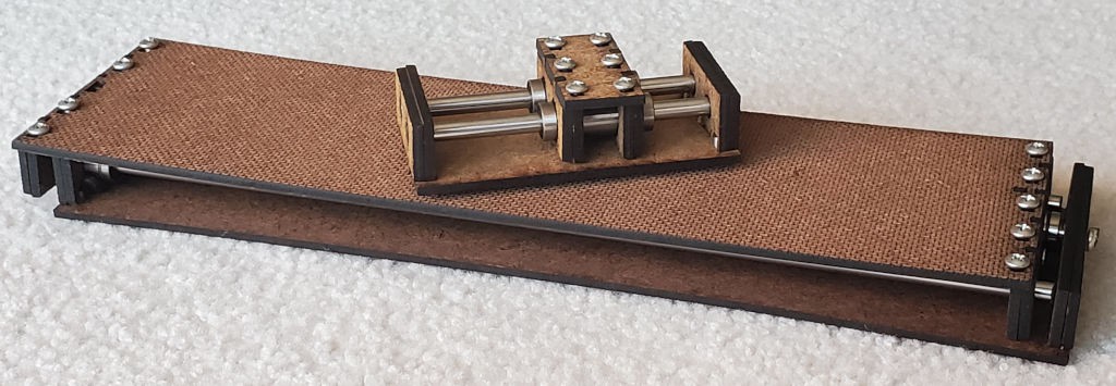
The very minimized example turned out fine. The go-for-broke long one successfully satisfied its purpose of revealing what would be its worst fault:
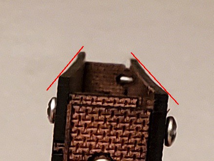
First try came out half baked. No surprise for making it mostly to see how bad it would be, and how it would be bad. Result: the ends pre-load bow into the sides (not new) and the silly-long bendy sides bow enough to interfere in the middle.
I have a couple of ideas to try for fixing that without adding a lot more material/bulk.
A slide has two plates at each end of each side of the slide: one plate with “V” features to locate the rods and bearings and a second plate to clamp the rods and bearings by pulling them firmly into the “V” features. The clamps pull and the “V” plates push. Magic parts would pull and push in the same plane. The real parts pull and push in offset planes, with the "V" plates on the outside and the clamps inside. The clamps pulling between the “V”s would tend to bow the middle of the rod closer to a rigid side plate. But here the rod(s) is(are) more stiff than the hardboard sides, so it’s the sides that get bowed inward toward the rods. As dimensioned for 100mm rods, the inward deflection of the side plates is barely visible and not enough to make trouble. When stretched to match longer rods, but with the same width and thickness, the long skinny sides deflected farther inward so that the two halves of the slide scraped against each other instead of running freely.
The obvious solution is to use appropriate material. But the game here is to get more from less. So continuing with the cheap stuff...
One of the "couple of ideas" was a bunch of ideas around the theme of stiffening the sides by adding a perpendicular element. That could be a simple stringer, or two, or making a box. Variations could grow overall dimensions in thickness or breadth by more or less. Boxing a side could potentially add torsional rigidity. One side could be boxed around the other, making something a little more conventionally "telescopic". I didn't actually do any of that, but will come back to structural stiffness a different way later in ̶ t̶h̶i̶s̶ a coming log entry.
The other idea was to neutralize bending forces by adding a third plate at each end, so that each end has a clamp pulling in between two adjacent "V" plates.
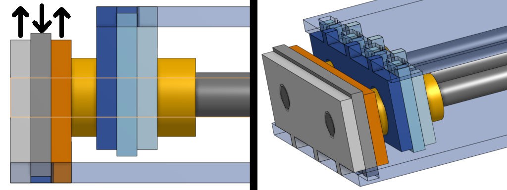
The basic design half-way does that already with small support crutches under the bearings. Because they don't bear torque well. In other words, the third plate is already in there, just mostly not there except under the bearings. Because supporting the rods also would reduce the range of motion by two material thicknesses and increase the minimum collapsed length by a thickness. That would reduce the range of motion of a 100mm motorized slide by ~10% for no benefit.
However, those penalties hurt less in a longer slide. This trial version won't have to actually do anything so it doesn't need room for anything but the three rods/bearing sets. So it's narrower as well as longer to fit 320mm rods. That makes the side plates even more skinny/bendy than the one that didn't work.
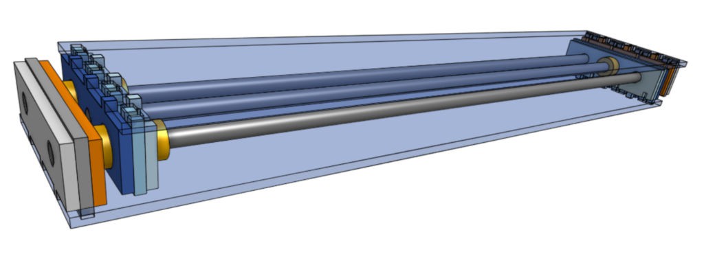
At maximum overlap the minimum overall length is 332mm and the fully extended length is 615mm. From the min & max lengths:
| stroke length = | 283mm |
| stroke length = | 85% collapsed overall length (vs. ideal 100%) |
| stroke length = | 46% maximum overall length (92% of ideal 50%) |
| minimum overall length = | under 120% of stroke |
| minimum overall length = | stroke + 49mm |
From a quick method-free search for commercial examples, it looks like stroke + d is a common spec for linear actuators (devices that expand/contract their overall length dimension) and examples of minimum overall length for 250mm stroke included + 125mm and + 250mm. Not rigorous, but so far the idea of minimizing dead length in excess of stroke seems to be holding up ok.
As I've already said a few times, I'm_continually_surprised by how not-badly these telescoping slides work at full extension, where the triangle of the three bearings collapses almost to a straight line with three bearings overlapping side-by-side nearly in a straight row, while at the same time the fully extended slide gets maximum leverage across the minimally offset bearings.
This pic, below, from the earlier log entry shows that version of stretched slide holding itself surprisingly close to straight while loaded right on the minimal overlap.
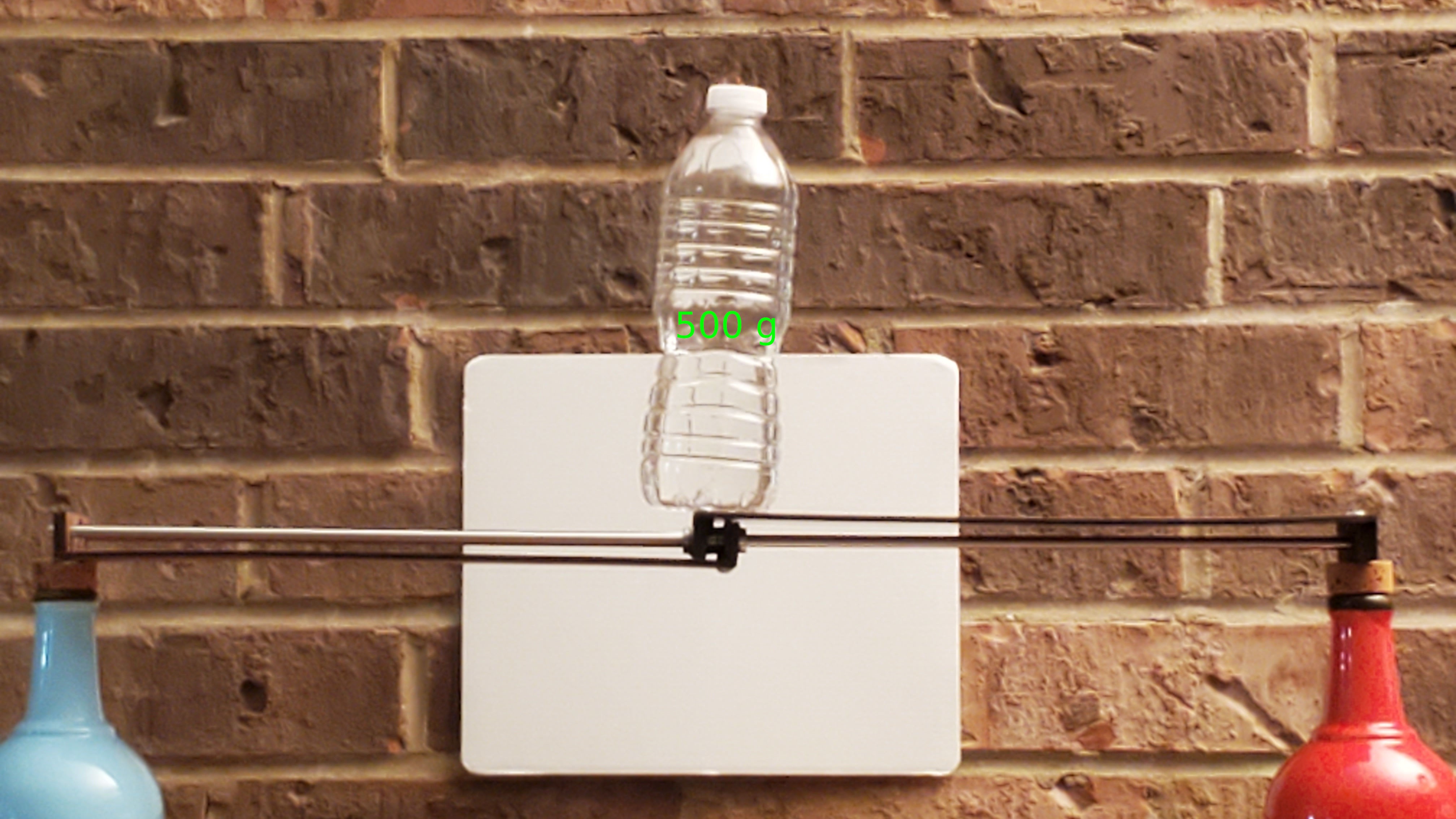
With a high-gain squint at that photo you might also see how the bowed sides prevented free motion through the mid-range of extension. That's the problem that this version solved:
Ok, I hafta finish this log. Coming in {the next,a future} episode: the best part is no part.
 Paul McClay
Discussions
Become a Hackaday.io Member
Create an account to leave a comment. Already have an account? Log In.