 Paul McClay
-
A try at additive fab
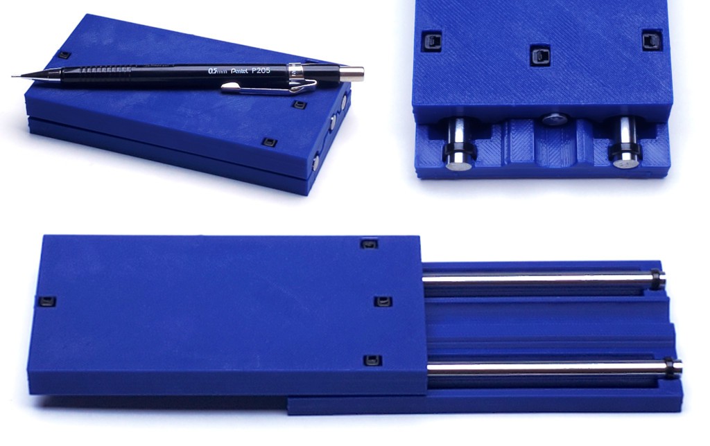
08/04/2022 at 03:37 • 0 commentsA first whack at re-rendering the basic idea for 3d printing...
![]()
...and experimenting with zip ties for assembly.
No axial stagger between rods when closed, so length overall = length of one rod = 120mm in this instance. Range of motion limited short by ~10% because I started the basic layout with an application in mind -- i.e. could be ~12% longer throw at max extension allowed by 19mm bearing length and ~7mm off each end of the rods for attachment. Two rods are packaged close together for best yaw resistance (lesson from a try at relaxing that) while breadth between those and third rod can be more or less per application.
-
Well, that's extreme: "Hacking any linear slide/bearing [...] make a nanoresolution piezo motor in 10 seconds"
06/12/2022 at 03:41 • 2 commentsJust gotta flag up this project: #Hacking any linear slide/bearing into piezo motor posted by @Edwin Hwu.
"Herein we present the design of an open-source XYZ-axis nanopositioning system. Utilizing a magnet-based stick–slip driving mechanism, the proposed XYZ nanopositioner provides several advantages, including sub-nanometer resolution, a payload capacity of up to 12 kg (horizontal), compact size, low cost, and easy assembly; furthermore, the system is adjustment-free. "
![]()
The project links to a journal article. The journal looks a bit like HaD with editorial standards and peer review. And it's open access. The existence of open access journals is something of a successful hack itself, but I am at risk of digressing further...
-
Long slides that work - part II
02/08/2022 at 06:06 • 0 comments...continuing, maybe even finishing, the log that's taking months to write...
Successful application of these slides requires loading them near the ends and avoiding any load in the middle of the flexibendy side plates.
Simply attaching a slide to something more rigid satisfies that constraint for free. Once the four corners of a side get screwed down it becomes as rigid as whatever it's attached to, without any further reliance on the flexible middle span of the side plate.
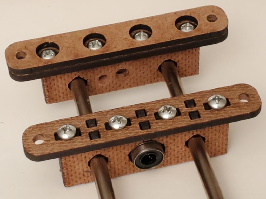
In that case, most of the side plate won't be missed:
![]()
"the best part is no part" — a famous entrepreneur That uses less material, much less for a long slide, and yields end assemblies that fit any length of rod. One kind of assembly could be used at both ends when the material in the space opposite the bearing isn't used.
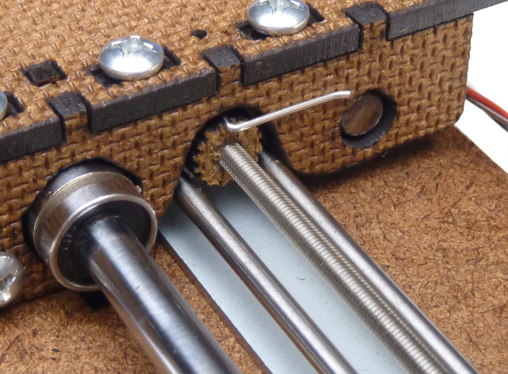
The shim plate keeps preparation of the mounting surface simple:
![]()
Drilling clearance pockets for the screw heads would work too. I've used the shim "feet" to concentrate complexity in the laser cut parts in order to keep other fabrication as simple as possible, and to chew up my base material less while iterating through several variations, but that's a choice for my motivating application. If used, clearance pockets should just clear individual screw heads and leave solid bearing surface under the V plates.
The end assemblies above may be assembled and incorporated into a complete, if fragile, slide, which can then be handled and mounted as a unit.
I also tried a variation of directly replacing the side plate with more robust material, without growing the end assembly to add mounting tabs or a shim plate. In this case by simply cropping the ends without alteration and adding the thickness of new material to the length of the screws. This version incorporates the heavier material directly in the slide construction and can't be assembled without it.
Here the cropped end of the side plate is kept for its laser-cut details. In principle, those details could be precisely cut into the heavier material, but availability of that capability might favor entirely different construction.
In line with keeping complexity in the laser-cut parts and out of other fabrication, the heavy material is simply cut to length and width. The laser-cut parts included a template of pilot holes (not shown) to guide sufficiently precise location of the drilled holes.
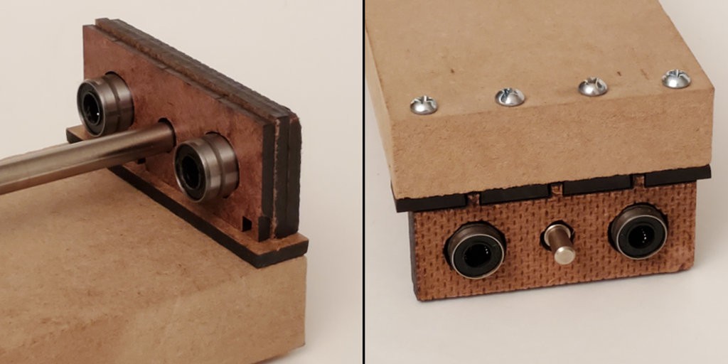
![]()
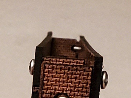
Aside: The two-view image above shows much more material in the clamping plate over the bearings than in any previous example. When fully extended these long slides have great leverage across the small remaining overlap in the center. Stressing the first example began to strain the thin bridge of material over the bearings. Because these separate end assemblies stand one or two material thicknesses higher above the side surface, they also gain that much additional clearance between the top of the clamp and the opposite side. In this example I used that additional clearance to add material to the clamp over the bearings.
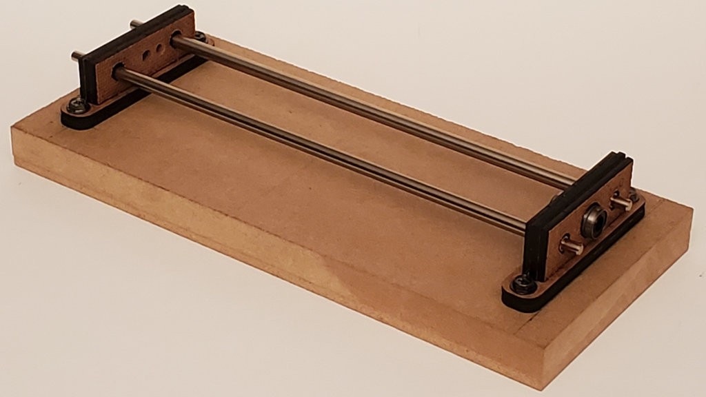
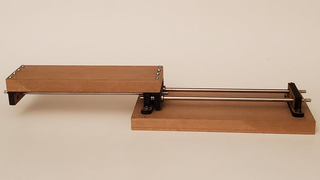
A complete slide using the parts above:
![]()
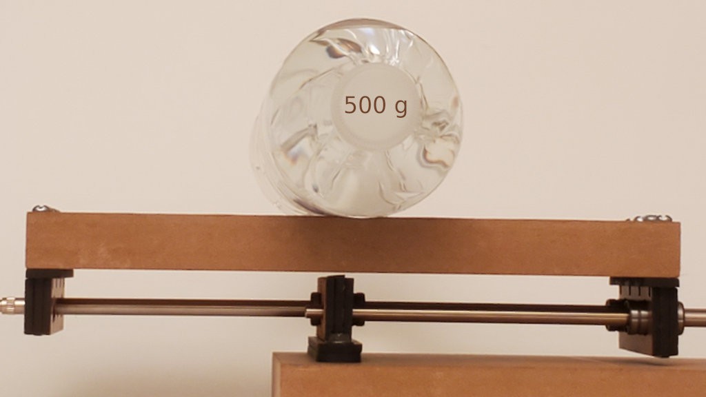
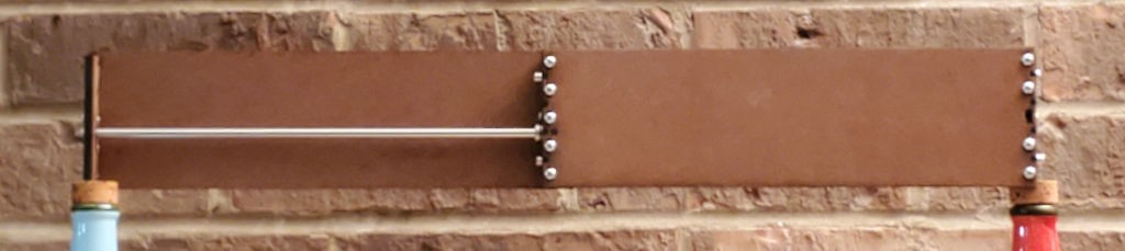
long sides that are not bendy This long side of this slide easily bears load in the span between the ends. In this case the long side of the slide is far more rigid than the long rods.
![]()
In this case the load carrying capacity is limited by the rods flexing when they are loaded in mid-span. As described above, I made the bearing clamps taller in this example. Using up less of the increased clearance for the clamps and leaving more room for the rods to flex would increase the load this slide could bear without scraping in the middle — when that much sag is acceptable.
The rods have turned/knurled ends because they came out of a printer.
From writing up my first try at a long slide:
It's really just the two ends in the middle constraining where the rods and bearings intersect the two nearly coincident planes that make the slide much more stiff than an equivalent span of hardboard.
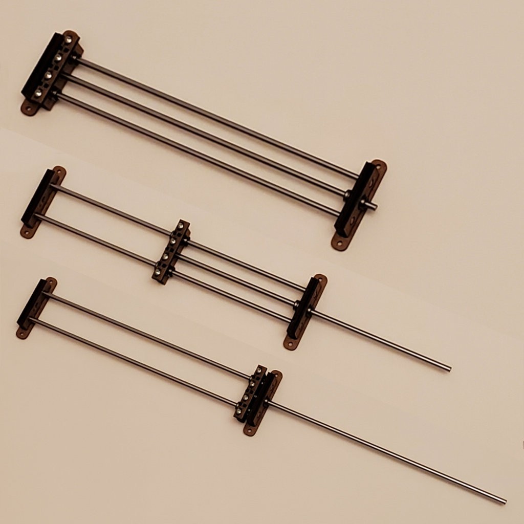
These separate end assembles — and only the three ends that hold relationships between two or three things — clamped onto rods make a complete, if delicate, slide:
![]()
That skeletal arrangement has the stiffness of this earlier example:
![]()
(apart from a flat place to park a load, and if not twisted)
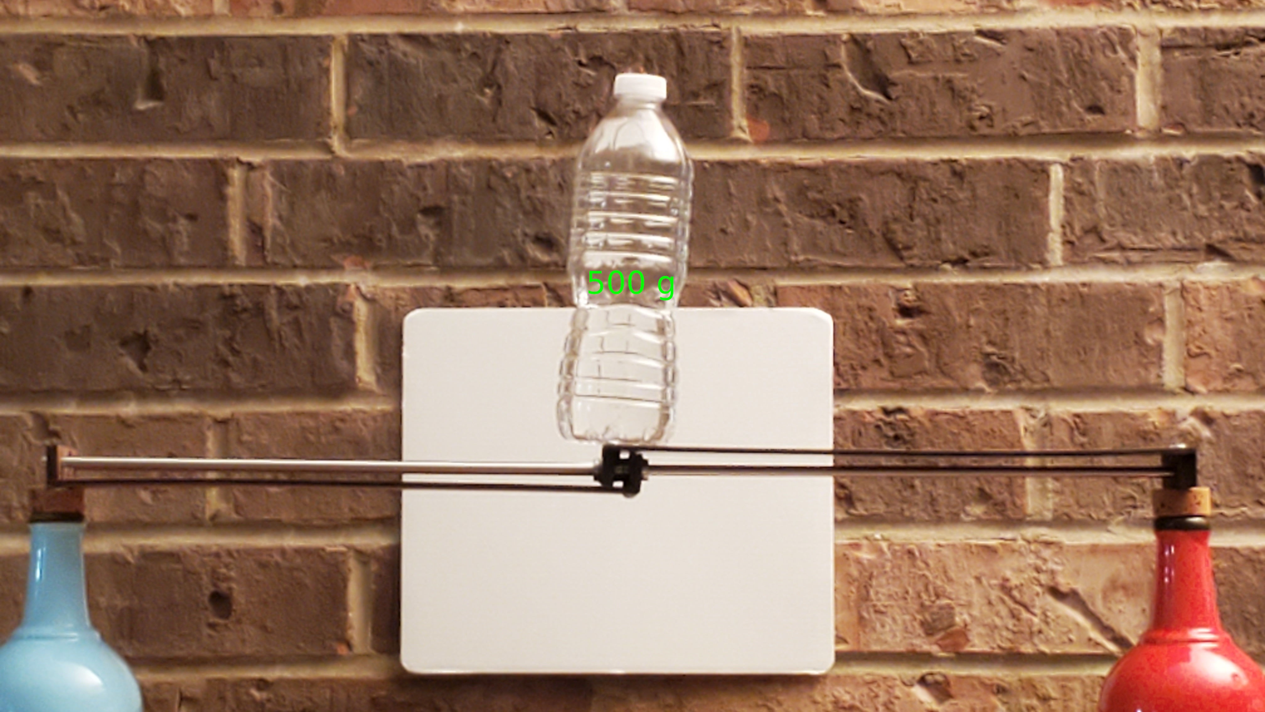
... and smoothness of this example:
![]()
...which I've repeated here because I'd rather finish this log than stage new photo examples!
-
Long slides that work
12/14/2021 at 20:41 • 0 comments
long slide runs smoothly all the way out to the end -- where short bearings overlap side-by-side -- and back From the start this project has focused on variations of a single basic design using 100mm rods. Late last year I experimented with reduced and stretched variations.

pic from the earlier log entry The very minimized example turned out fine. The go-for-broke long one successfully satisfied its purpose of revealing what would be its worst fault:
First try came out half baked. No surprise for making it mostly to see how bad it would be, and how it would be bad. Result: the ends pre-load bow into the sides (not new) and the silly-long bendy sides bow enough to interfere in the middle.
I have a couple of ideas to try for fixing that without adding a lot more material/bulk.
A slide has two plates at each end of each side of the slide: one plate with “V” features to locate the rods and bearings and a second plate to clamp the rods and bearings by pulling them firmly into the “V” features. The clamps pull and the “V” plates push. Magic parts would pull and push in the same plane. The real parts pull and push in offset planes, with the "V" plates on the outside and the clamps inside. The clamps pulling between the “V”s would tend to bow the middle of the rod closer to a rigid side plate. But here the rod(s) is(are) more stiff than the hardboard sides, so it’s the sides that get bowed inward toward the rods. As dimensioned for 100mm rods, the inward deflection of the side plates is barely visible and not enough to make trouble. When stretched to match longer rods, but with the same width and thickness, the long skinny sides deflected farther inward so that the two halves of the slide scraped against each other instead of running freely.

...or a little more internal clearance would make that deflection harmless The obvious solution is to use appropriate material. But the game here is to get more from less. So continuing with the cheap stuff...
One of the "couple of ideas" was a bunch of ideas around the theme of stiffening the sides by adding a perpendicular element. That could be a simple stringer, or two, or making a box. Variations could grow overall dimensions in thickness or breadth by more or less. Boxing a side could potentially add torsional rigidity. One side could be boxed around the other, making something a little more conventionally "telescopic". I didn't actually do any of that, but will come back to structural stiffness a different way later in ̶ t̶h̶i̶s̶ a coming log entry.
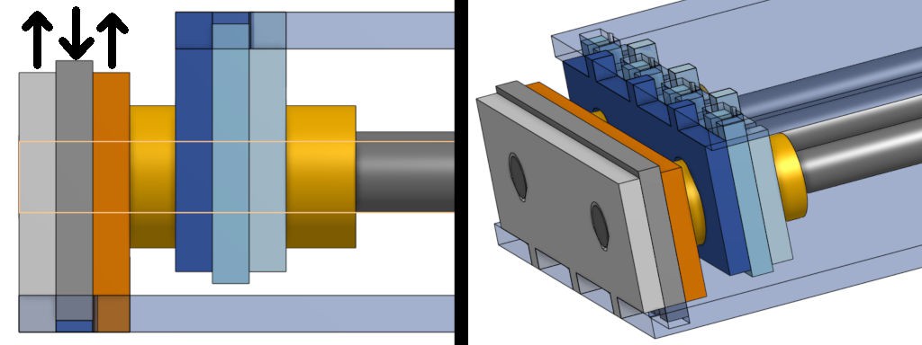
The other idea was to neutralize bending forces by adding a third plate at each end, so that each end has a clamp pulling in between two adjacent "V" plates.
![]()
The basic design half-way does that already with small support crutches under the bearings. Because they don't bear torque well. In other words, the third plate is already in there, just mostly not there except under the bearings. Because supporting the rods also would reduce the range of motion by two material thicknesses and increase the minimum collapsed length by a thickness. That would reduce the range of motion of a 100mm motorized slide by ~10% for no benefit.
However, those penalties hurt less in a longer slide. This trial version won't have to actually do anything so it doesn't need room for anything but the three rods/bearing sets. So it's narrower as well as longer to fit 320mm rods. That makes the side plates even more skinny/bendy than the one that didn't work.

l[Oo0]+ng slide At maximum overlap the minimum overall length is 332mm and the fully extended length is 615mm. From the min & max lengths:
stroke length = 283mm stroke length = 85% collapsed overall length (vs. ideal 100%) stroke length = 46% maximum overall length (92% of ideal 50%) minimum overall length = under 120% of stroke minimum overall length = stroke + 49mm From a quick method-free search for commercial examples, it looks like stroke + d is a common spec for linear actuators (devices that expand/contract their overall length dimension) and examples of minimum overall length for 250mm stroke included + 125mm and + 250mm. Not rigorous, but so far the idea of minimizing dead length in excess of stroke seems to be holding up ok.
As I've already said a few times, I'm_continually_surprised by how not-badly these telescoping slides work at full extension, where the triangle of the three bearings collapses almost to a straight line with three bearings overlapping side-by-side nearly in a straight row, while at the same time the fully extended slide gets maximum leverage across the minimally offset bearings.
This pic, below, from the earlier log entry shows that version of stretched slide holding itself surprisingly close to straight while loaded right on the minimal overlap.

another re-heated pic from the earlier log entry With a high-gain squint at that photo you might also see how the bowed sides prevented free motion through the mid-range of extension. That's the problem that this version solved:
Ok, I hafta finish this log. Coming in {the next,a future} episode: the best part is no part.
-
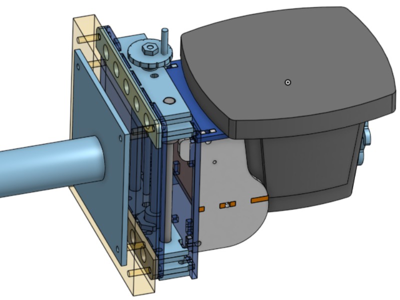
Application: StereoZoom-to-VESA mount+focus slide
11/10/2021 at 01:13 • 0 comments![]()
ProblemEveryone needs a stereo microscope! Because ... ... they cost less than space tourism.
But not everyone has several unallocated hundreds of US$ to trade for one with useful characteristics like low-to-mid “zoom” magnification and useful field of view at a useful working distance.
Alas. What to do?
Solution
@w_k_fay showed the way: #Stereo Microscope For Around $100 ! Briefly: Bausch & Lomb StereoZoom models, particularly StereoZoom 4, filled the Earth for 60 years[a] and now supply an abundant resale market. For example: mine.
Problem with the Solution
That’s great, but there’s a catch.
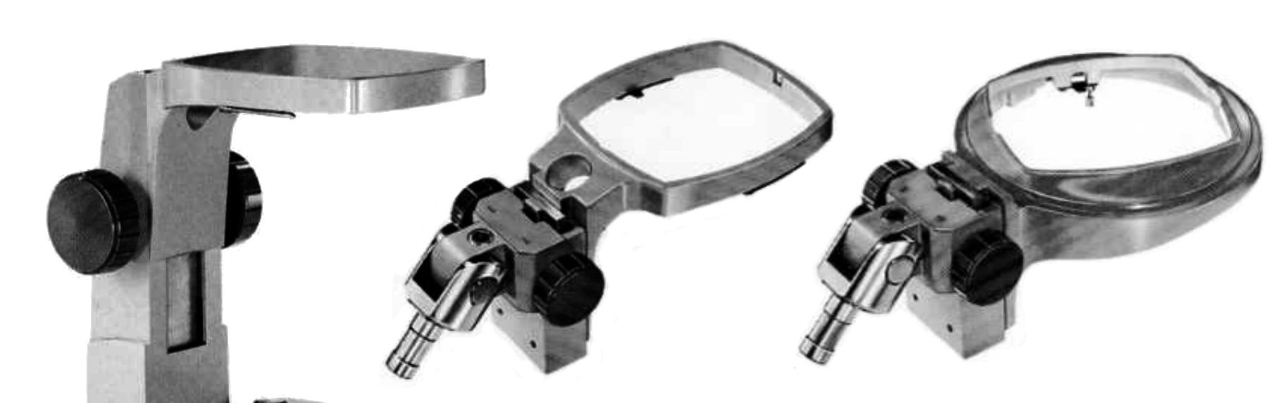
B&L StereoZoom microscopes consist of optics in a “Power Pod” held by one of a variety of stands. The catch is that the irregular shape of the “pod” defies simple attachment to anything other than a B&L stand.

Bausch & Lomb StereoZoom Power Pod ![]()
Bausch & Lomb widgets that can hold a StereoZoom Power Pod Whatever holds the pod also has to be able to adjust focus by moving the pod up & down (or axially in whatever orientation) with some precision.
And
In markets like famousAuctionsite, "Around $100" will fetch a lot more bare pods than pods with stands.
Solution to the Problem with the Solution
So what would hold an awkwardly shaped object and provide finely controlled linear motion along it's axis?
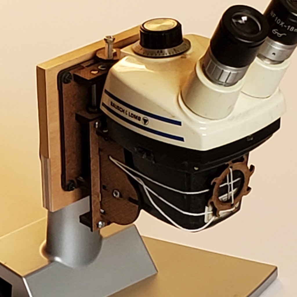
How about something like one of these cheap linear slides with a tool clamp, except with the detachable/interchangeable clamp swapped for different clamp parts shaped around the awkward "Power Pod" shape? That screwed to a block with a e.g. a 75mm VESA pattern of pilot holes screwed to an arbitrary monitor stand should do it...
![]()
[a] made by B&L then Leica from 1959 to 2000, then NYOPTICS/oem-optical.com sold a “top quality remake” until at least September 2019 according to the Wayback Machine
-
variations little & long
11/05/2021 at 08:37 • 0 commentsTrying some variations on the theme...
Little:
Using long (LUU) bearings on two rods instead of three. Trades range of motion for simplicity. No room for internal motor but simple enough to make wider for an externally driven leadscrew.
As of writing this, I haven't published the CAD model yet.
Long:
Just bigger #rodl in the published model...
![]()
First try came out half baked. No surprise for making it mostly to see how bad it would be, and how it would be bad. Result: the ends pre-load bow into the sides (not new) and the silly-long bendy sides bow enough to interfere in the middle.
![]()
I have a couple of ideas to try for fixing that without adding a lot more material/bulk.
Once again I'm surprised by how not floppy the slide is at full extension - even with the extra-long sides gaining multiplied leverage across the extremely short overlap. Of course long narrow strips of hardboard flex easily so the overall result is far from "rigid", but even at full extension the tiny overlap holds up better than I would believe if I wasn't holding it myself.
![]()
The bendy sides only have to maintain relative orientation of the ends. It's really just the two ends in the middle constraining where the rods and bearings intersect the two nearly coincident planes that make the slide much more stiff than an equivalent span of hardboard. Kinda neat, IMO.
The sides don't bend so much edgewise, but slide the mechanics allow a tiny bit of free rotation (yaw) at minimum overlap (bearing motion almost tangent to rods). The very long sides exaggerate that, allowing the middle to deviate ~1mm to either side. It's palpable but doesn't look bad at arms length:
![]()
(the mill has motors inside the slides so they never get to minimum overlap)
-
Would you like tabs with that?
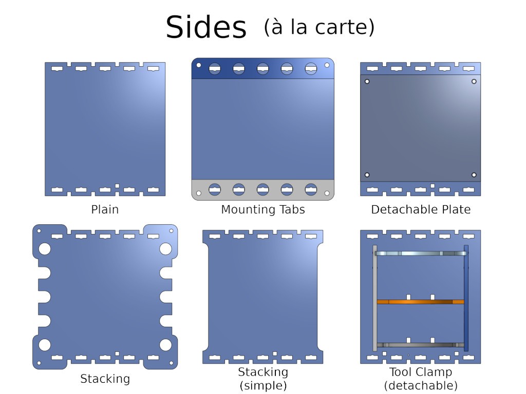
05/25/2021 at 09:05 • 0 commentsThis shift in concept of application accidentally slid in while working on the motivating application for this project.
![]()
The concept in my head from the start had been to model an internally configurable, externally featureless slide as a generic reusable component. For use by carving up the side plates, either literally with tools or in CAD or vector drawing to adapt the part for an application before before making it in the first place.
While working the application side of this idea -- the proverbial eating my own dogfood -- I eventually got the clue that a useless default defaults to useless when the universe of applications grows beyond contemplating how it might be applied. Derp. ("Plain" is close to useless because there's nearly no clearance on the inside of the plate for anything like a screwhead -- and I disparage hot glue/epoxy/etc enough to not want to eat that crow)
So it makes sense to provide at least one way to do something.
The "Stacking (simple)" side-cuts were half a nod at that after I stopped trying to keep the slide narrower than the length between the rows of screws at each end. The side cuts allow units to fit together across each other but left attaching them as a problem for later. They also take material away from where bendiness is already a compromise.
So that's the set-up for the Slow Dawn of the Obvious:
- attach slide side to something else
- attach slide side to side of another slide
- attach something else to slide side
are a small option space that cover a big fat most of what there is to do. (where "spoil board" is the degenerate case of attaching something to the slide)
And picking from a short list once for each side evades thinking about how many combinations are actually plausible.
The clamp for a specific rotary tool breaks from the idea of general utility, but a uniform clamp/slide interface teases the possibility of a more general/adaptable clamp or general way to roll your own specific clamp. (update: like this!)
CAD & 'ible updated (the 'ible still needs some finishing up re rigging and using the clamp - as of writing this)
-
Build instructions that I don't already plan to re-do. !.
04/23/2021 at 07:34 • 0 commentsOk, I've managed to finish re-writing an Instructable without already having the next necessary re-write in mind. Yay!

Build yer own! Lemme know how it goes! The last couple of logs included:
[Update: but the 'ible is the Better Way. (...and I've thought of a futher simplification, I think...)]
then:
Coming soon: another rev for easier ease of assembly, and [...]
I rilly wanted to get this done. But writing isn't my thing and this slowed me down for a good long time. Now maybe back to actually doing stuff...
-
Stackable
04/12/2021 at 20:42 • 0 commentsSlides stack easily for 2d.
![]()
Manual slide on top at full extension holds mass cantilevered far off the side of a powered slide. Bottom slide doesn't care.
Coming soon: ̶a̶n̶o̶t̶h̶e̶r̶ ̶r̶e̶v̶ ̶f̶o̶r̶ ̶e̶a̶s̶i̶e̶r̶ ̶e̶a̶s̶e̶ ̶o̶f̶ ̶a̶s̶s̶e̶m̶b̶l̶y̶(done), and a refresh of #Minamil: a minimal CNC mill.
A Cheap Compact Linear Slide
<$10. <10μm repeatable. >10kg capacity. Laser-cut 1/8" hardboard. For 100mm x 6mm rod, but semi-parametric. Handwheel or stepper drive. CAD.


