 Matthew Begg
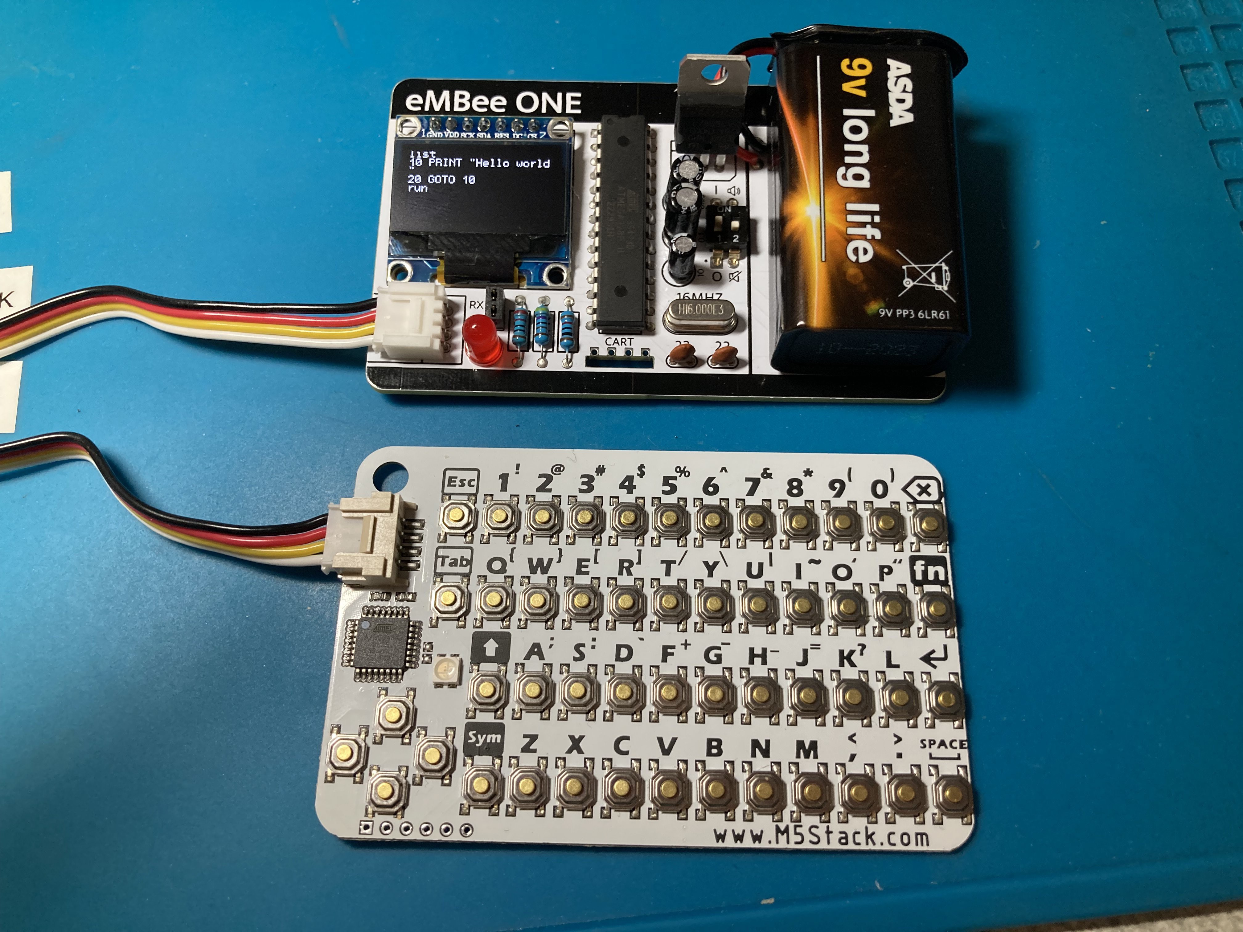
I've now built the first 'production ready' eMBee ONE using one of the 5 Rev A boards I got from JLCPCB. There was a tense moment before I flicked the power switch on for the first time and...
...it worked!
There are a number of issues that I'll definitely need to sort out before they're ready to distribute:
- The board is too wide to fit in an Altoids tin! It's 85.6mm which is apparently the correct size for a credit card, but compared to the CardKB it's about 2mm too wide. So revision B will be 83.6mm wide. Other dimensions are fine.
- As mentioned before, the RX/TX pins are a bit pointless without a GND connection, so the next revision will have 3 pins instead of 2.
- The introduction of 'eMBeeLINK' communications means the list of commands and functions will need updating to include SEND and RECV$
- When I tried to solder in a 28-pin DIP socket, the two rows of pads were too far apart. So I had to solder the chip directly onto the board. Not a good idea for the finished product, so I'll need to use a narrower part in the design so the socket can be used
- Similar issue with the on/off switch - ended up snapping the legs off one before getting the bend just right. So the pins need to be closer together on this.
- Speaking of the on/off switch, it's only now I've got it in place next to the tall capacitors and 9V battery that I realise how incredibly hard it is to reach! You have to have baby fingers to get to it. So in the next revision I'm going to move it - probably swap it with the 4.7K and 10K resistors.
- Even though I was snipping the extra length of leads after soldering components, the board still stands proud of the surface it sits on. So I'm going to investigate small rubber feet for the corners. Maybe even stretch to 4 more for the keyboard too.
- The L7805 voltage regulator looks so massive - I'm going to source a smaller TO-92 package version to make better use of the limited space on the board. This might free up space for more ports.
- The markings around the keyboard port look a bit wrong so I might remove those.
- Once the 9V battery is in place, it completely covers up the programming header. So I'll need to move that further down.
Hopefully won't take me long to get those issues ironed out and get a new set of boards ordered. In the meantime I'm super pleased that the general design works! Still to test:
- The speaker (I forgot to solder it in BEFORE adding the screen - oops)
- The cartridge slot
Discussions
Become a Hackaday.io Member
Create an account to leave a comment. Already have an account? Log In.