As I'm already 1.5 years into this project, but missed to write anything up, this is a mix of an overview on the project and a mostly chronological log.
Some Design choices
As I most often use ATMega uCs in my projects, I decided to stick to that here as well.
As the 96x96px Sharp Memory-LCDs are not in production anymore, I use the newer LS013B7DH03 128x128px display. This means I need some RAM for the framebuffer. Thus the choice of the ATMega 1284P as uC.
As my analog design-skills are limited (and RF skills practically non existent), I decided to use an integrated module, the Microchip RN4871, that also brings some certification. That of course means this watch will never reach a power consumption as low as an NRF or STM32 standalone solution with integrated radio would allow. However, a couple of days of runtime should be OK, and it's still a learning project.
The RN4871 cannot be used with the maximum of 4.2V expected from the Li-Ion cell, hence a 3.3V regulator is needed. Also, according to the datasheet the ATMega is not guaranteed to run stable at 16MHz and 3V. However, I need to be able to communicate with 115200 baud to the RN4871. Hence, the main clock frequency of choice is 7.3728 MHz allowing for no baud rate error at 115200 baud and stable uC operation.
The main sensors are provided by an LSM303 (magnetometer, accelerometer).
First (round) version
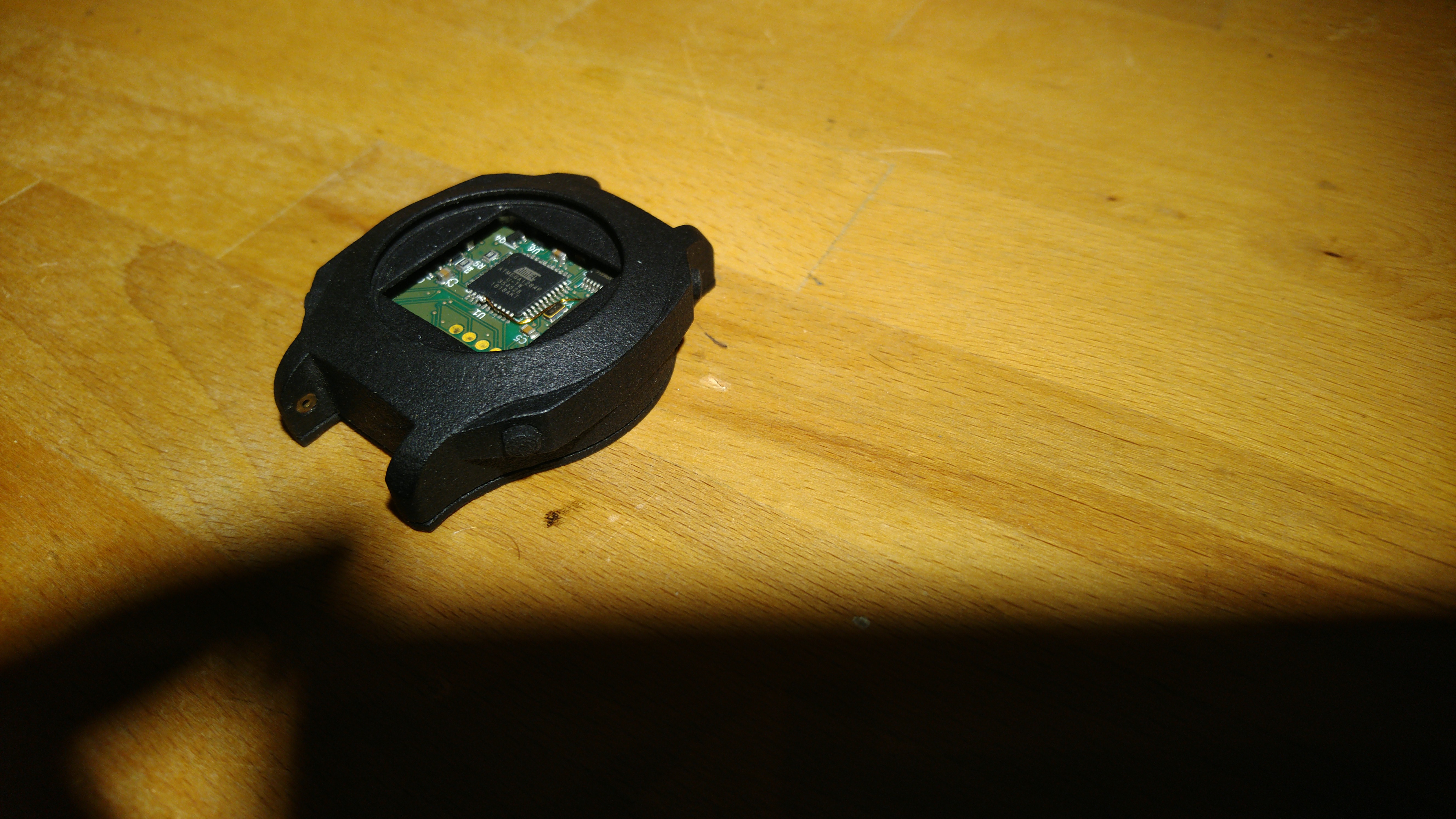
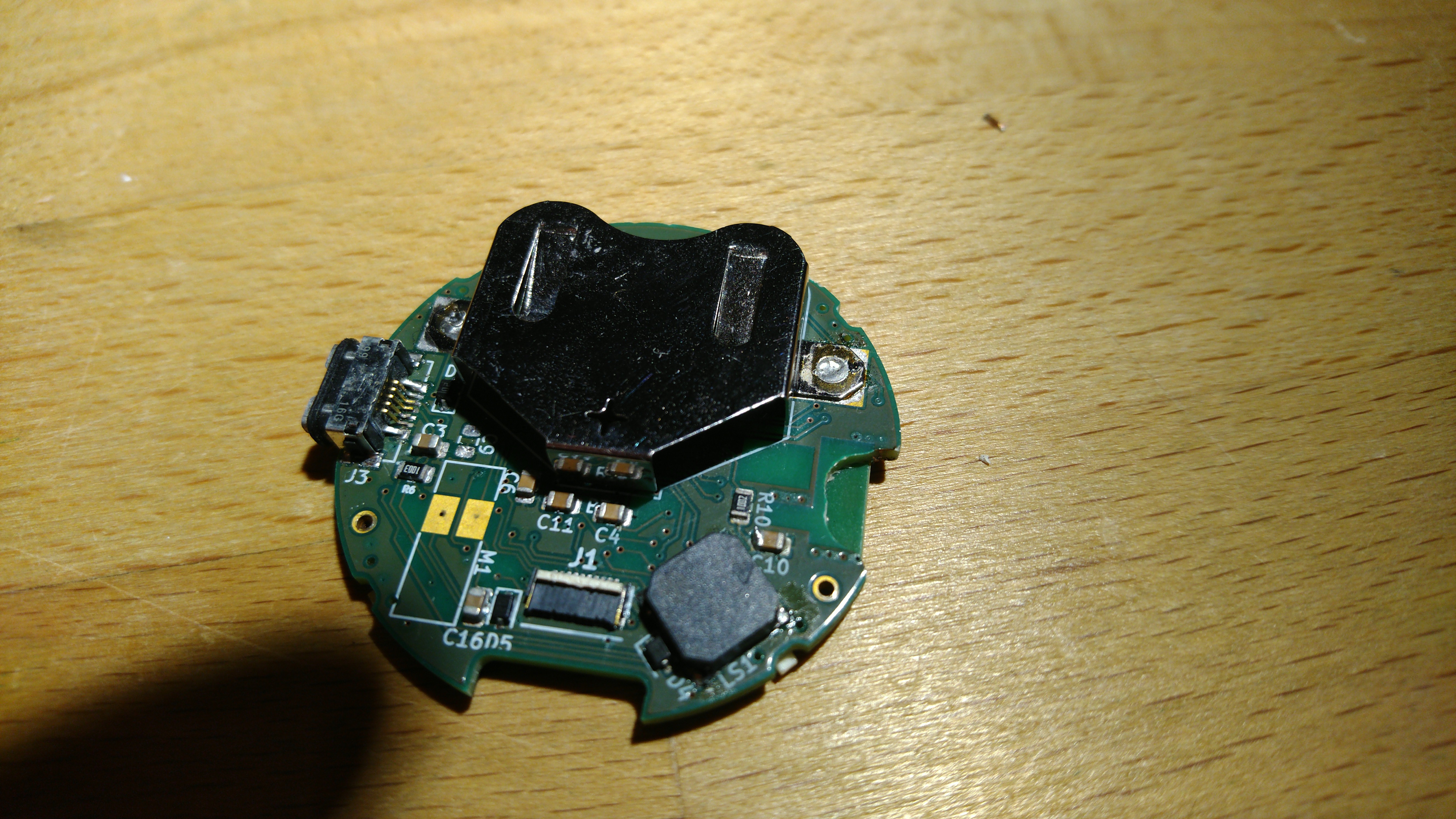
As I do not like rectangular watches too much, the first version was designed as a round watch with an outer case diameter of 46mm (yes, uff quite large). I liked Max.k's idea of using coin cells as you can get replacements everywhere, but due to the higher consumption I decided to use a quite large rechargeable LIR2450 lithium ion cell. Due to the respective coin cell socket this lead to a pretty large 17mm body height. So this design was very unhandy as a watch, but left enough place to fiddle around and fix mistakes I made in the first design.
The case was 3D printed with HP Multi-Jet Fusion (means I ordered it instead of printing it myself). My FDM printer doesn't allow for sufficient surface quality on the overhangs. The buttons, back cover and glass are sealed with o-rings. The o-ring is also what keeps the glass in place. (The above image doesn't show glass and display as I already scavenged those for the second version). Arguably, o-rings don't really seal on a rough 3D-printed surface, but it's better than nothing. From a mechanical point of view this worked great. The buttons were easy to push and you needed serious force to press the glass out of the case. Only the back was a little too thin to provide sufficient pressure on the o-ring all around the circumference, but the missing pressure was supplied by the arm while wearing.
Programming and charging are both done via a waterproof micro usb connector (which is also quite large).
As a backlight I found the integrated modules by FLEx lighting to be the easiest option (FLEx lighting 11049-03).
In order to keep the BOM short I thought I'd stick to the internal RC-oscillator as main clock for the uC (not for time keeping). This means the RC oscillator is calibrated to approx. 7.3728 MHz on each boot based on the 32kHz clock crystal on Timer2 (PDF ATMEL AppNote). This worked pretty well, but takes some time during booting and I wasn't able to fit the calibration code into the Bootloader. That means the bootloader runs on the regular, inaccurate 8MHz clock and thus the programming transfer rate is limited to 9600 baud. This is quite unnerving when fiddling on small things in the code.
In addition to the vibration motor the PCB features a CUI piezo speaker, but after testing the watch for a couple of days I decided that I don't need a speaker if I have a sufficiently strong vibration motor. Also the speaker takes up quite a lot of space on the PCB.
Besides some quirks (as discussed in the following list) the hardware worked pretty well.
Anyway, I of course made a lot of mistakes and learned a lot from this first version:
- Having the reset pin of the RN4871 module controllable from the uC is important, as this allows for resetting the communication protocol into a known state (data mode /cmd mode)
- The RN4871 can directly change the level of an output pin based on the data written to a BLE characterisic, even in low power mode. This is handy, because the UART doens't work in low power mode and this additional pin allows the cell phone to signal the watch that it has news for it without keeping the BLE module awake all the time.
- somehow I had a typo when calculating the resistor (3k instead of 10k) for defining the charge current of the battery (a factor of three too high). Thus, batteries didn't survive long.
- While the o-rings worked pretty well, I underestimated the porosity of MultiJet Fusion prints. Usually this didn't have an effect, but when cycling in the winter the watch is cooled by the wind while sweat penetrates the porous bottom cover. The result is condensation on battery, and the whole PCB, resulting in usually a dead battery. So there's room for improvement.
- The point above brought up another point. Sometimes I noticed something is wrong with the watch (condensation), but could not kill its power to stop draining the battery as I only included a soft power-off controlled by the uC (that of course didn't work as the uC clock was hanging due to condensation). So without tools to take out the battery I had a problem. The solution is simple: include a real pushbutton on/off controller IC (e.g. LTC2955), instead of my finicky discrete solution with passives and diodes.
- This is just too large for a watch to wear everyday (at least for me). So probably there is a reason that many smartwatches are rectangular, following the outline of the used display.
- I should use a ceramic resonator for the 7.3728 MHz clock. This still allows for a relatively fast clock startup after powersave, but makes everything more stable, easier, and increases the programming speed to 115200 baud via Arduino IDE.
- Fiddling with the bootloader was exhausting because I had the respective ICSP pads on the display side of the PCB. So I always needed to take apart the whole watch to reprogramm the bootloader. While this is reasonable if everything was fixed and it's a working everyday watch, this is not reasonable for a tinkering project. Hence, the ICSP lines need to be brought out of the case as well.
- While I had the display data connector on the bottom side of the PCB so I could first tighten display and PCB and then connect the display, the connector for the backlight was on the other side of the PCB. This was necessary because of the coin cell socket's large footprint, and makes putting everything together a quite complex task, because the backlight needs to be connected first, then the USB socket is fiddled into the cutout, and with nearly no space left the display underneath needs to be carefully pushed with fine tweezers into place. This process is prone to damaging the display.
- I accidentally looked at the wrong figure in the RN487x datasheet when designing the low impedance copper plane around the module. Therefore, I unfortunately extended it beyond the antenna section. This of course limited the signal strength quite a lot. So to improve on that I desoldered the RN4871 module, milled the respective portion of the PCB, and resoldered it (see image below). This resolved the issue.
I'll upload some stl files of the casing to give a better idea of the watch. The schematics of this version are more like a sketchbook and therefore I don't want to publish them here. (I won't put work into cleaning them up either, better wait for version two).
As a short remark on the software
I first set up a very ugly arduino project that simply included readily available Arduino libraries (RN487x, AdafruitGFX+AdafruitSharpMemLCD, Sodac LSM303AGR). This proved that all the hardware worked. Then I let this code grow over the next year until it became an unstable, unreadable mess. However, it already provided BLE communication with a similarly ugly companion app which I wrote for my SailfishOS device.
So finally while waiting for the components of the second version I decided to rewrite the whole code. Everything is now modular to a certain degree, and there are "apps" (libraries with functions following a template which are then called from the main script). As I somehow wasn't able to make the AdafruitSharpMemLCD library work with hardware SPI (for fast screen refresh) I also decided to rewrite a new graphic library. This worked quite well, however my code might seem a little bizarre for Arduino users as I wanted to stay compatible to C (no function overloading etc) for later being able to compile the same source with the Arduino IDE (C++) or with standard C (which I usually use for uC projects). However, this is not yet achieved and there are many things still incompatible with C. Also the BLE library is rewritten to better match the use case (hopefully more secure bonding), but is not yet finished. So while the watch function surpass the old ugly version the current version cannot yet communicate with a smartphone.
I still need to change some stuff to use the external AdafruitGFX Font (instead of the font I copied together in the current code), before publishing this.
But as a preview: the higher framerate of the graphics library allows for some fun raycasting (already with the second watch version):
Its controlled by tilting the watch. That's why I have to tilt it away from the light sometimes. My initial Raycaster was much too slow. Therefore, thanks for the great tutorial Lode.
Second (rectangular) version
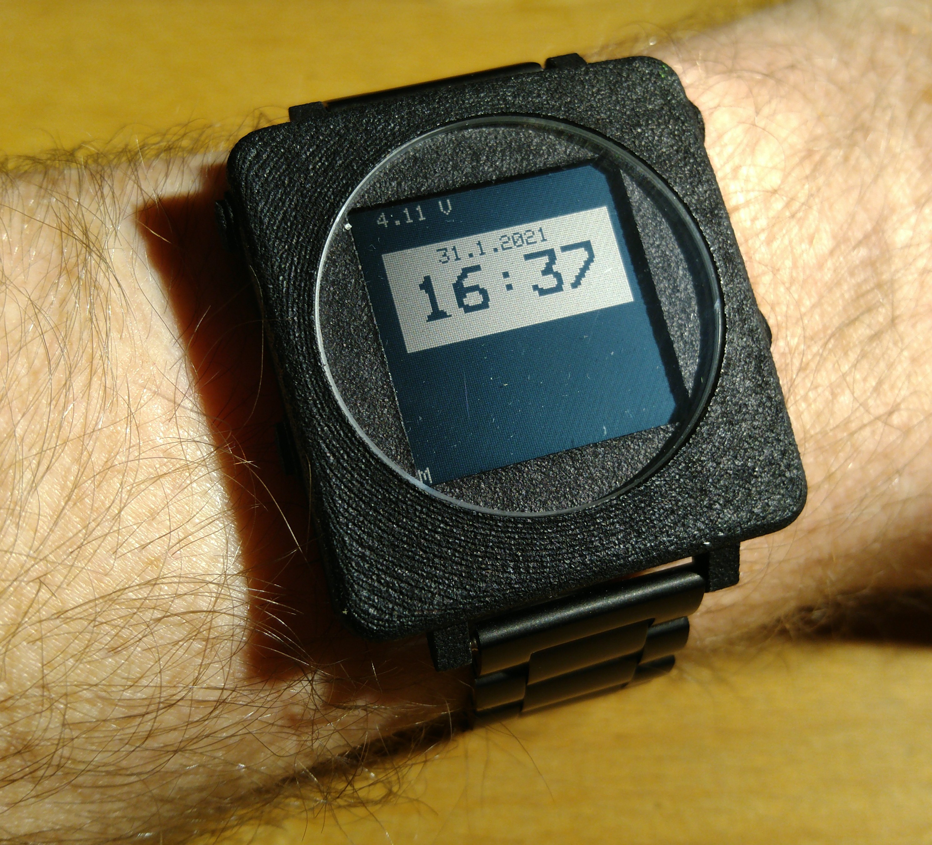
In the second version I of course tried to resolve the issues of the first one. The result is rectangular and smaller (body WxLxH 40x42x13.3mm). Unfortunately the print quality turned out a bit worse (maybe due to the more delicate design? I don't know). For shrinking the watch I had to switch from 0805 passives to 0603 passives and also leave some stuff out: there is no speaker anymore and several discrete components where replaced by a LTC2955 Pushbutton on/off controller.
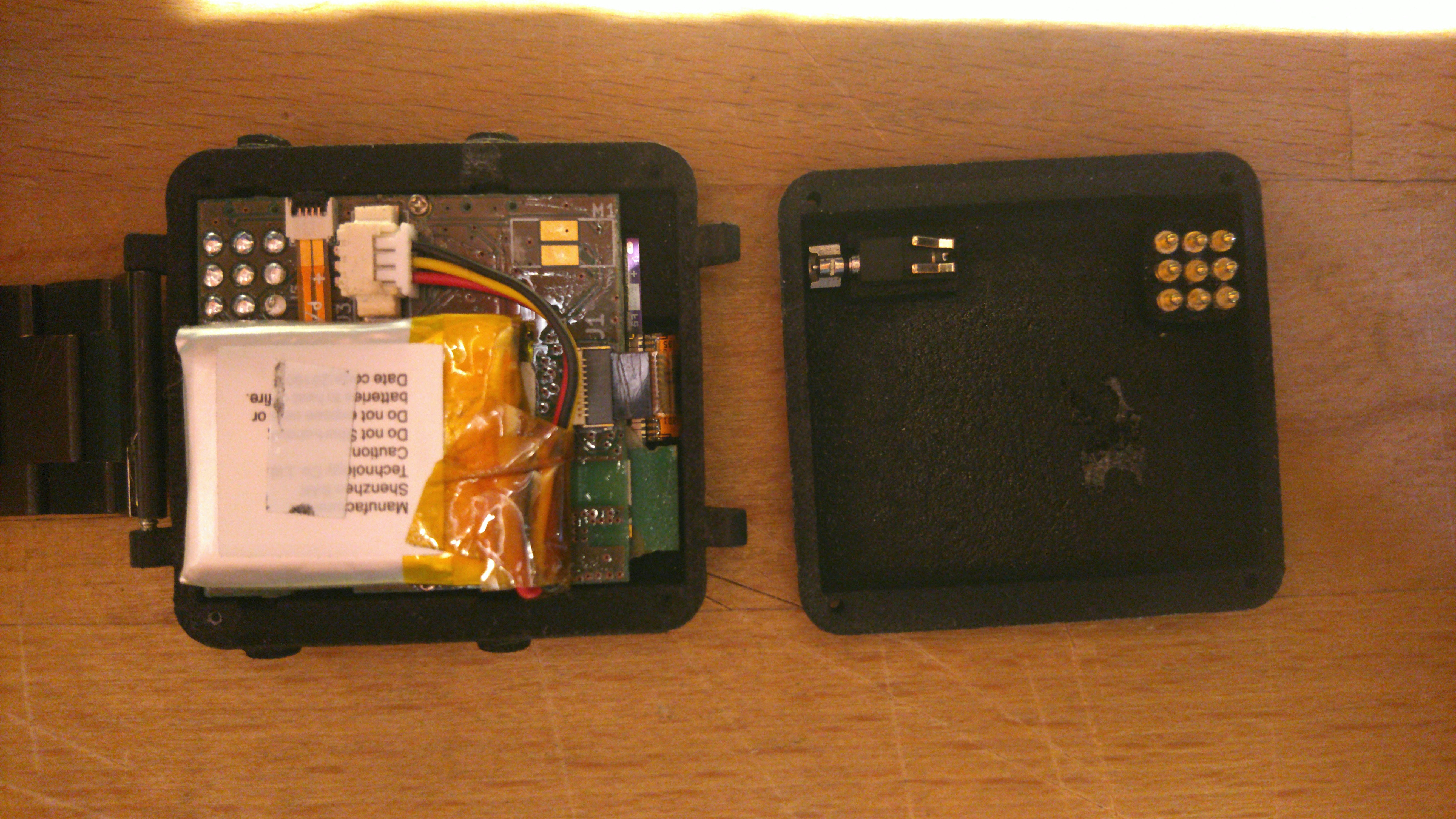
The general sealing concept is the same: o-rings for buttons and glass. To cope with the porosity of the case I decided to use a modified silicone conformal coating on the PCB. This works very well but stays quite sticky even after hardening, such that I always have to carefully peel of the display from the PCB when disassembling. I also coated the inside of the bottom case half with this spray to keep out any unwanted water vapor in the future. The two casing halves are not yet sealed, but as soon as I'm confident that I don't have to open it again I will also apply a little conformal coating on the contact surfaces. As it stays quite sticky I hope this will suffice.
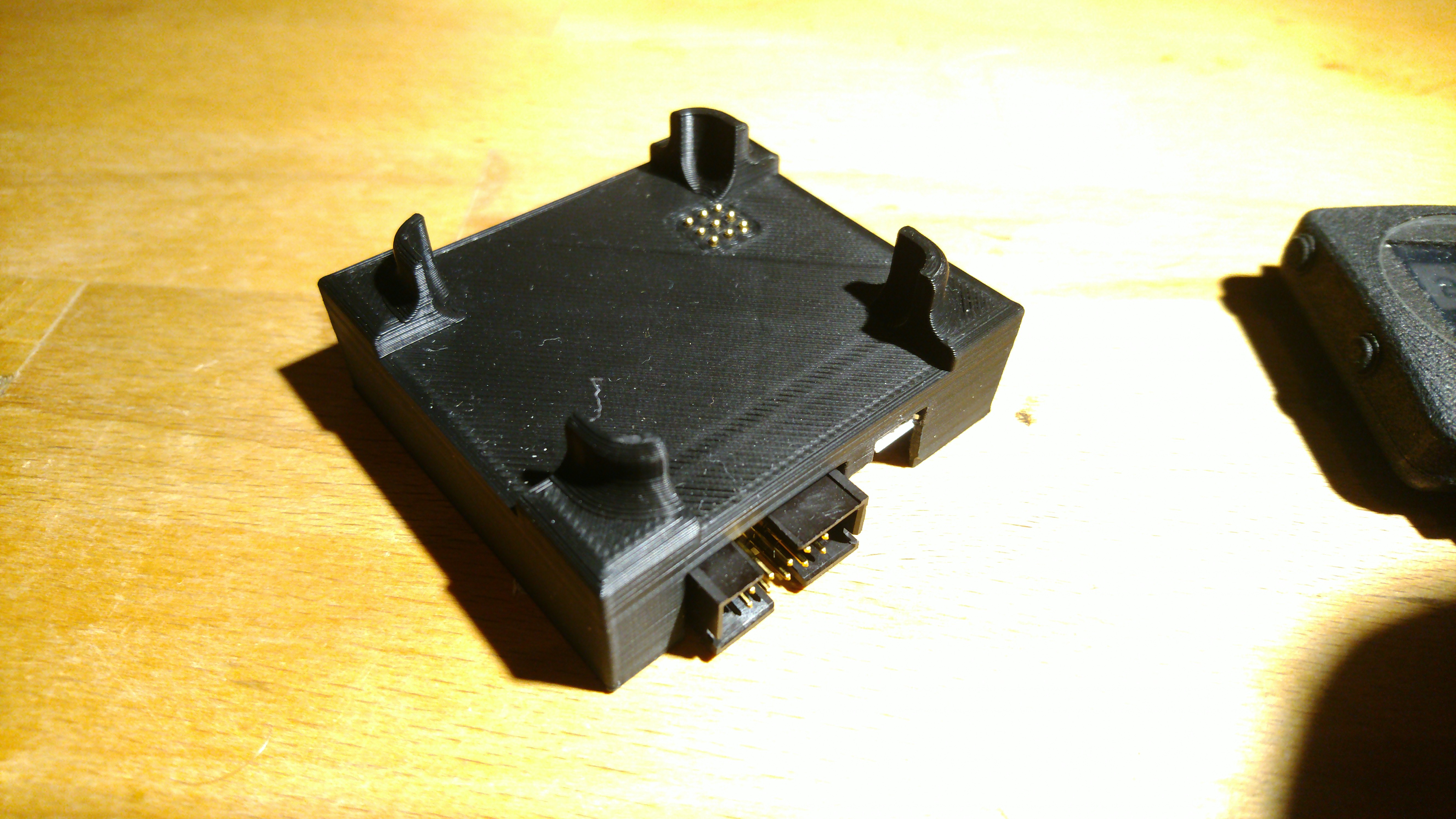
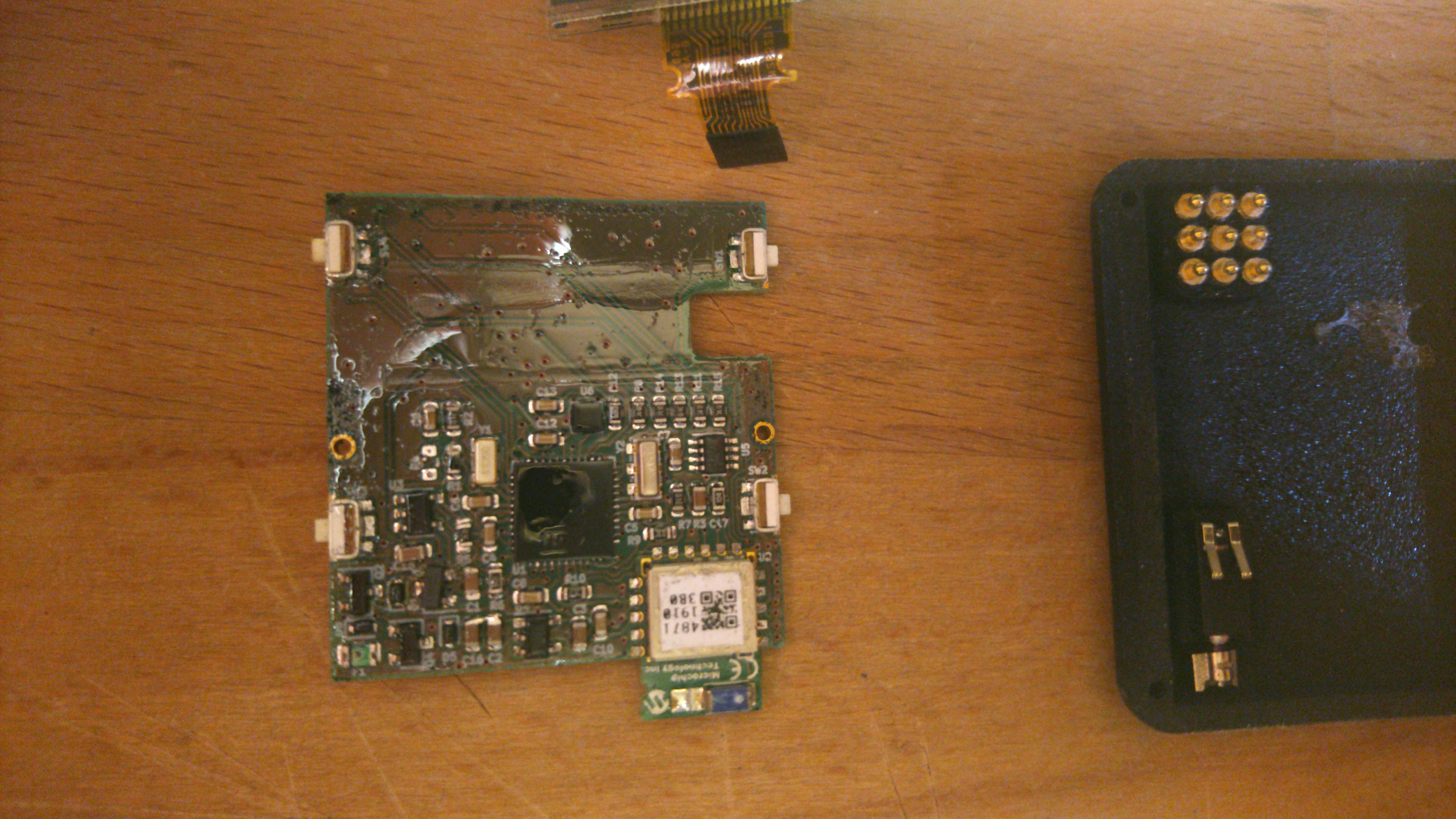
There is no USB socket anymore. Instead there are 9 pogo pin pads on the bottom of the watch that connect to the pogo pins in a dock. The dock also includes the FTDI FT230X USB-UART bridge for Arduino style programming and a 10-pin ICSP connector for in circuit programming with any standard AVR programmer. The pads in the watch case actually are themselves the bottom of pogo pins that are glued into the case and touch pads on the watch PCB. See the pictures for more details. I had to tin some of the contact pads on the PCB as the case shrunk a bit and didn't guarantee proper contact to the pogo pins.
The PCB is now a lot more compact and I'm quite happy with the results. The reflections on the PCB are caused by the conformal coating:
I only had one last mistake on the PCB which I didn't find during DRC because I accidentally deleted a power wire in the schematic. However this was easy to correct with a solder bridge.
As discussed in the text on the first version I added a ceramic resonator with 7.3728 MHz for making things easier. I'm currently using it but maybe I'll switch back to the RC-oscillator and save some (high consumption) CPU cycles during wake-up from powersave.
I uploaded the corresponding STL files and the schematics.