Evan
Evan-
LineageOS 21 KonstaKANG is working
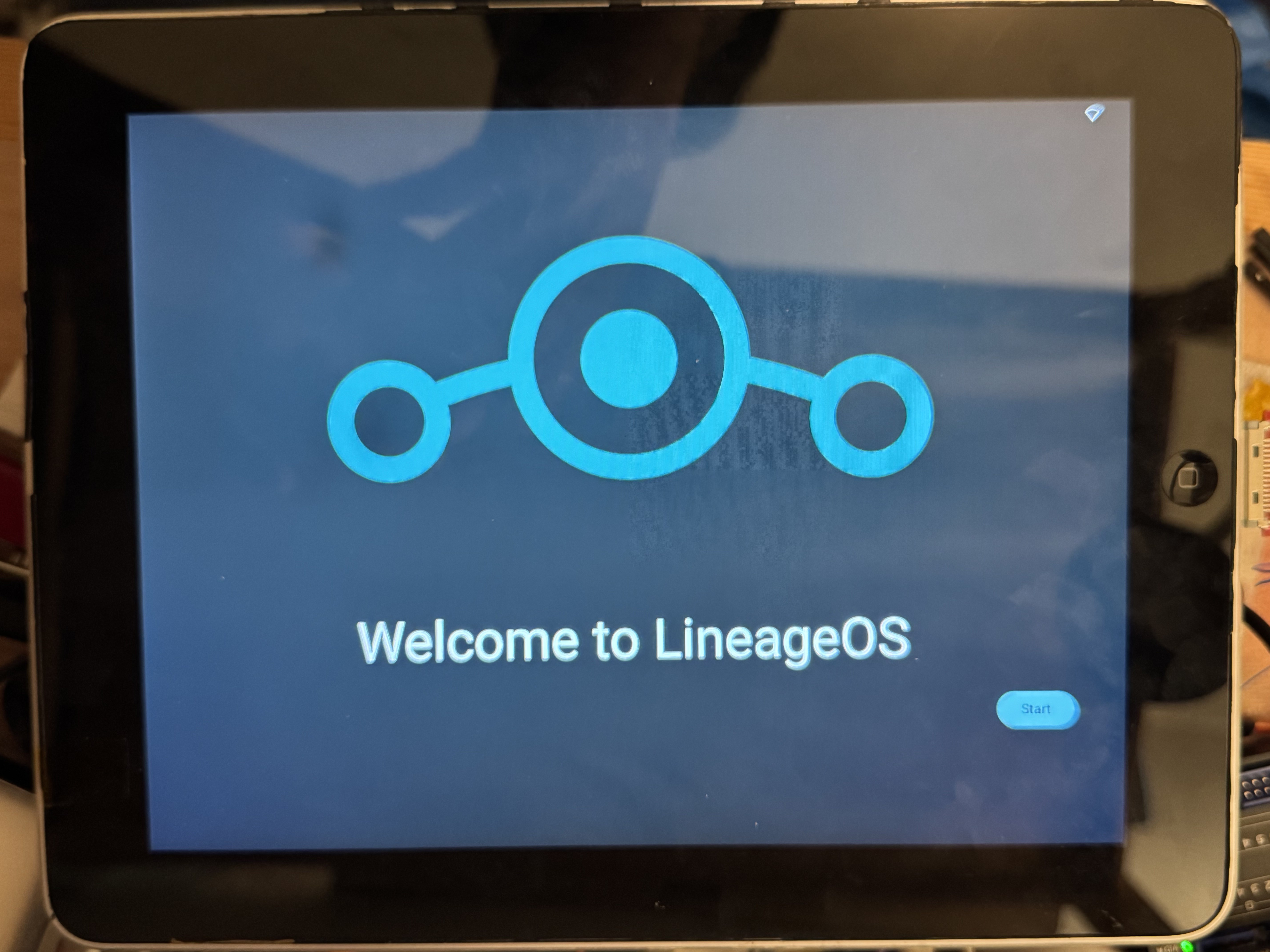
10/24/2024 at 07:23 • 0 commentsI was able to get KonstaKANG's build of LineageOS 21 (Android 14) working on the Pipad!
![]()
It's an almost-stock image, but I had to make a few changes to the kernel:
Backport the sn65dsi83 driver (the bridge that converts MIPI-DSI from the Pi to the LVDS that the LCD wants) from my raspberrypi-linux kernel (which is 5.15) to my fork of the raspberry-vanilla kernel (The backported driver was for the Radxa CM3. I'll try to post an update about that soon.) - Copy the appropriate dtoverlays over
- Set a few things in config_user.txt:
# User specific config.txt options
dtoverlay=gpio-shutdown,gpio_pin=22,active_low=1,gpio_pull=up,debounce=10
dtoverlay=gpio-poweroff,gpiopin=25,active_low=1
dtoverlay=gpio-key,gpio=22,keycode=116,label="POWER"

dtoverlay=vc4-kms-dsi-ti-sn65dsi83
dtoverlay=pipad-touchscreen
dtparam=spi=off
Fortunately, the raspberry-vanilla kernel already comes with the Goodix touchscreen driver installed, so I didn't have to do anything to the pipad-touchscreen dtoverlay.
I've only got a few bits of hardware integration working at the moment -- just the bare minimum:
- LCD and touchscreen work.
- The power button turns off the screen. (Ideally it would pull up a power menu?)
- It does not, however, turn the screen back on. I think it's trying to, but the sn65dsi83 isn't being reinitialized properly or something.
- When the system shuts down, it toggles the correct GPIO pin to disable the boost converter which converts battery voltage to 5V.
I got stuck for a little while where it would only display the boot animation on the LCD, and never progress past this -- it seems this was due to my CM4 only having 1GB of RAM (KonstaKang says you need at least 2GB.) I purchased a CM4 with more RAM, copied the disk image from the old CM4, and it booted up first try.
I'm super excited about this! A proper touchscreen-oriented OS is a much nicer experience using than trying to use Raspberry Pi OS. The on-screen keyboard pops up when necessary, all the tap targets are appropriately sized, etc. KonstaKang seems to have done an excellent job with e.g. hardware acceleration. Everything is super smooth, including Youtube playback in the browser.
This is my first time using LineageOS (or any custom Android image), so I still need to learn a ton. I'd like to get GApps installed (but need to be able to get into TWRP first, so I need to expose a GPIO pin on one of the buttons). I might also play around with the AOSP build, to see how that differs.
Hardware integration TODO list:
- I need some way of toggling a GPIO pin that I can use to boot into TWRP mode (for doing low-level Android recovery-mode stuff). For some reason, on this revision of the board, I connected all the physical buttons to the i2c GPIO expander except for the volume-down button, which is connected to nRPIBOOT (so I can use usbboot without having to open up the device). I can probably just add a bodge wire from one of the other buttons to one of the spare GPIO pins on the CM4.
- Device trees + put drivers into the kernel for:
- RTC
- Audio codec
- I expect this will be a whole pile of fun.
- Ambient light sensor
- GPIO expander (for the other buttons)
- More gpio-key dtoverlays for all the other buttons, so that they get mapped to keyboard events
- Battery charger
- Potentially cherry-pick my kernel patch for the HDQ protocol to get battery levels
- Figure out how to control the backlight from the Android UI.
- I can control the backlight from the CLI by editing /sys/class/backlight/backlight/brightness, so I'm not sure what needs to happen in Android-land.
- Improve the behavior of the power button.
- either make it shut down (or hibernate, ideally), pull up a software menu that would let me shut down, or fix the issue with it not being able to reenable the screen.
-
Identifying the ambient light sensor
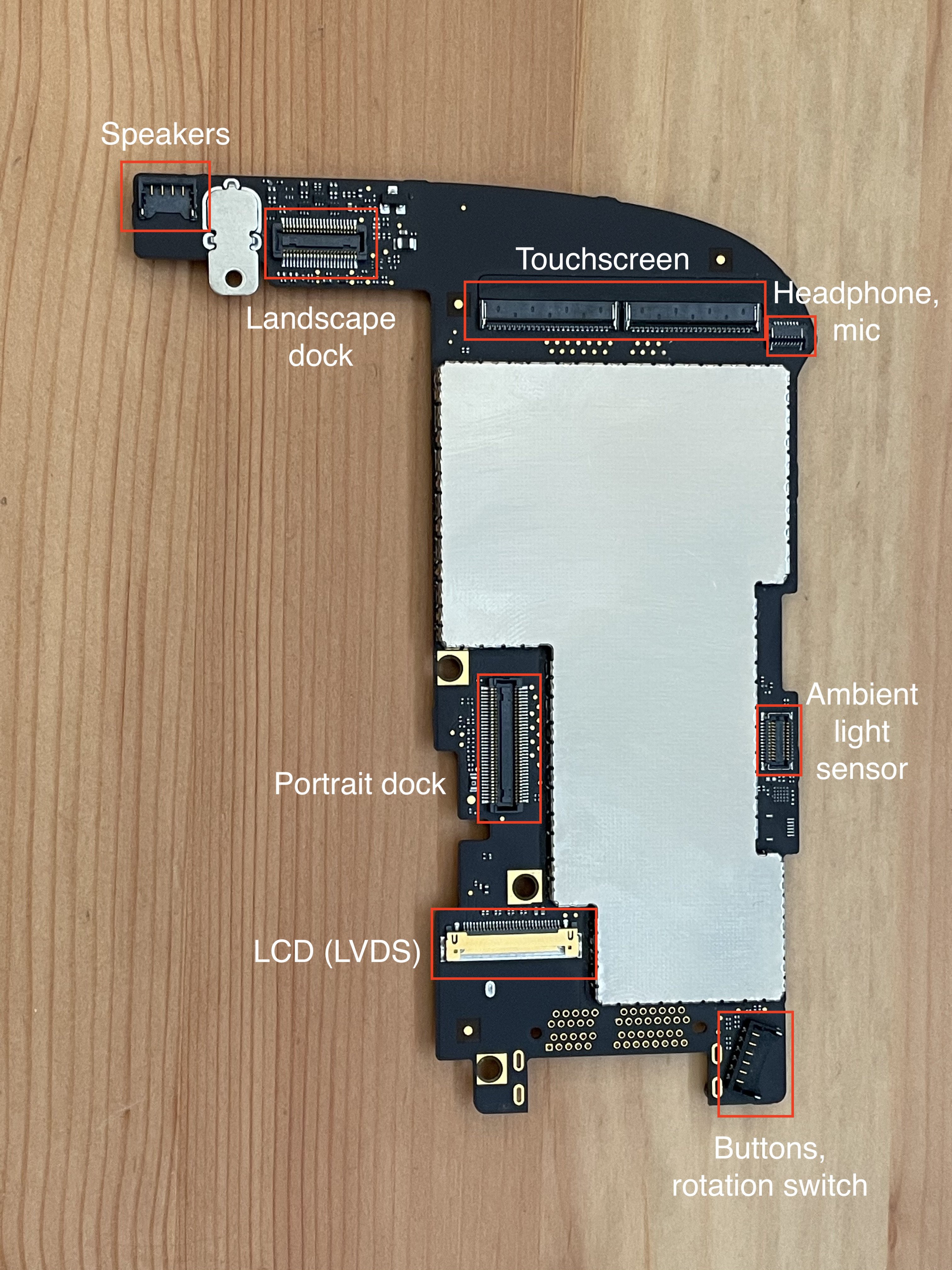
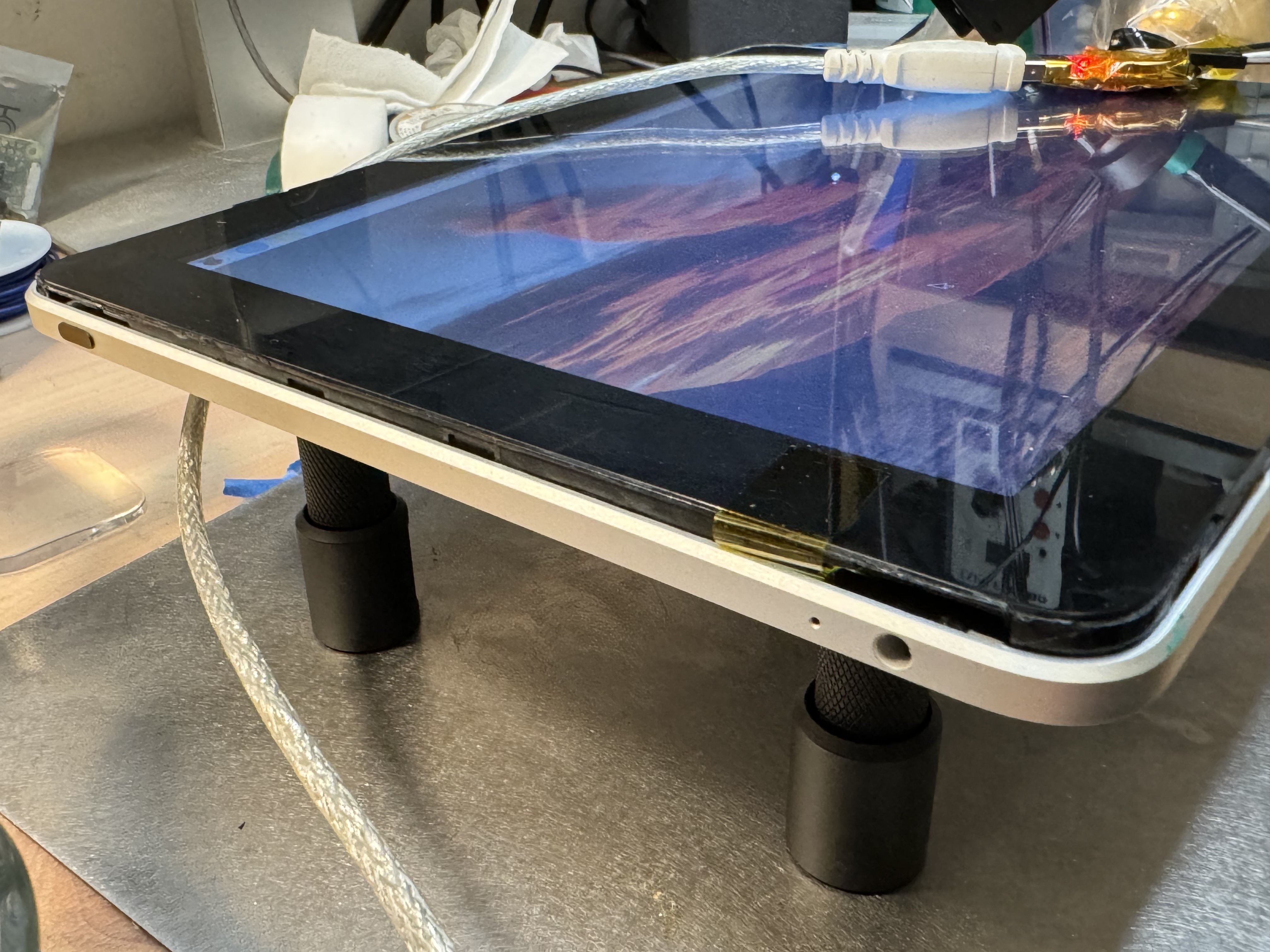
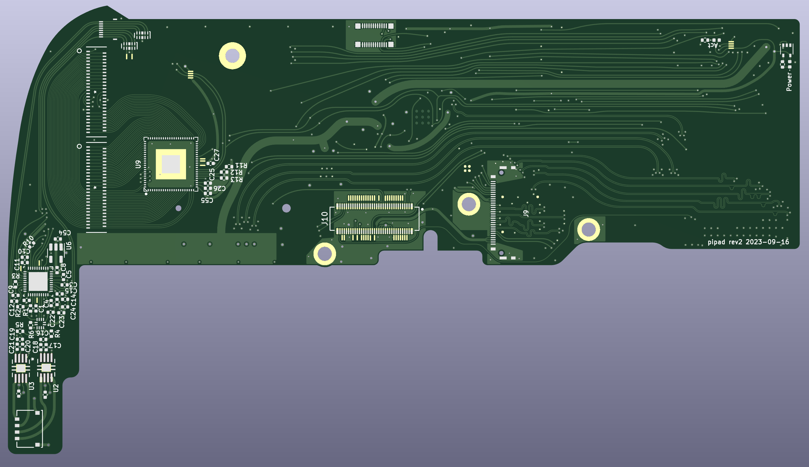
03/05/2024 at 05:39 • 0 commentsI've long been ignoring the ambient light sensor flex cable that's part of the iPad's display assembly. This connects to a 24-pin board-to-board connector on the logic board, pictured on the right edge here:
![]()
Only 7 of the 24 pins are used:
- 3.0V
- SCL and SDA for i2c
- ALS_INT_L
- COMP_RST_L
- COMP_INT_L
The other 17 pins are ground.
(Fun fact: this connector, the AA03-S024VA1, is also what they used for the camera in the iPhone 3G, though with a different pin configuration. Maybe they had a lot of extras and decided to reuse it on the iPad. It's not like they were low on space in the iPad, so using a larger-than-necessary connector wouldn't be a big deal.)
The last two pins are connected in the iPad schematics to "COMPASS_RST_L" and "COMPASS_INT_L",
I've been including this connector in all my prototype PCBs, and I also created a breakout board for it. This weekend, I wired up the breakout board to a Pi 4 (just power and I2C, none of the interrupt/reset pins) and got to work trying to figure out what ambient light sensor IC is used.
What's i2c address 0x39?
By wiring up the breakout board and connecting it to a Raspberry Pi, we can see that this cable only seems to have one device on it, at address 0x39:
meatmanek@pi4:~ $ i2cdetect -y 1
     0  1  2  3  4  5  6  7  8  9  a  b  c  d  e  f
00:                         -- -- -- -- -- -- -- --
10: -- -- -- -- -- -- -- -- -- -- -- -- -- -- -- --
20: -- -- -- -- -- -- -- -- -- -- -- -- -- -- -- --
30: -- -- -- -- -- -- -- -- -- 39 -- -- -- -- -- --
40: -- -- -- -- -- -- -- -- -- -- -- -- -- -- -- --
50: -- -- -- -- -- -- -- -- -- -- -- -- -- -- -- --
60: -- -- -- -- -- -- -- -- -- -- -- -- -- -- -- --
70: -- -- -- -- -- -- -- --
That's odd. I was expecting two devices: one for the compass, one for the ambient light sensor. Maybe it's a single IC?
Searching the internet for "i2c address 0x39" brought me to https://i2cdevices.org/addresses/0x39 which gives us a few options:
- APDS-9960 - IR/Color/Proximity Sensor
- PCF8574AP - I²C-bus to parallel port expander
- SAA1064 - 4-digit LED driver
- TSL2561 - light sensor
- VEML6070 - UVA Light Sensor with I2C Interface
Hmm. 3 of those could be ambient light sensors (APDS-9960, TSL2561, VEML6070), but also surely there are more devices out there that use this address.
Not wanting to tear apart my iPad more than necessary, I took another look at iFixit's images of this flex cable:
Enhance:
![]()
Enhance:
![]()
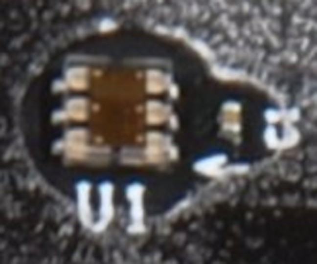
Looks like there's just one IC and a decoupling capacitor.
Here's what we know about this IC:
- It's the ambient light sensor.
- It's a 6-pin DFN footprint, but the size is hard to determine.
- The top of the chip is clear, exposing the die. (Makes sense for a light sensor.)
- We can see the 6 bonding wire pads.
- It uses I2C.
- It supports a power supply voltage of 3.0V
(I guess the compass may have been removed before the iPad shipped?)
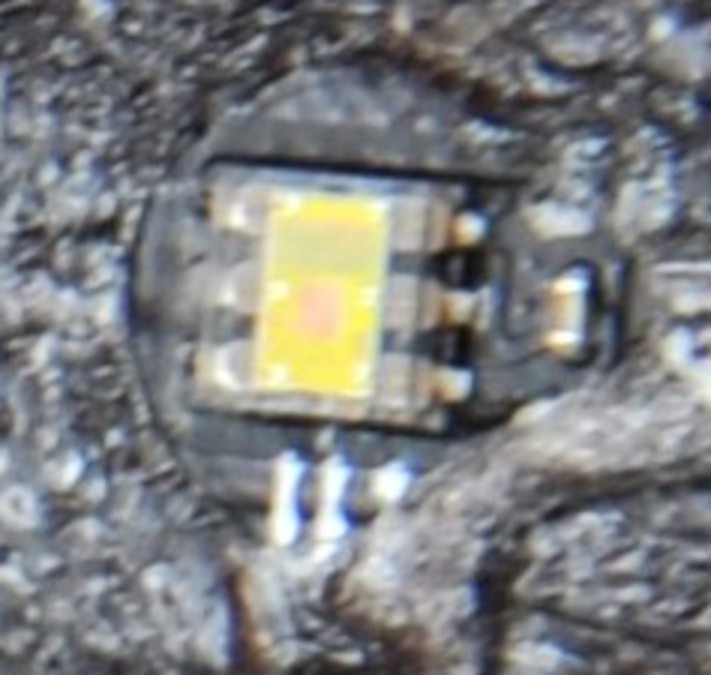
Looking at the three options from i2cdevices.org:
The APDS-9960 does RGB and gesture detection, and doesn't look right:
![]()
The APDS-9960 has a black plastic shroud, which our IC doesn't have. Also it has too many features to be an ambient light sensor. The VEML-6070 is a UV sensor, which doesn't make sense, and also it doesn't look right:
![]()
The TSL2561 looks promising:
![]()
The TSL2561 seems to be the right shape, not obviously the wrong color, and is the right kind of IC (Luminosity/Lux/Light sensor) To check if this is correct, I got the Adafruit python driver for this chip:
meatmanek@pi4:~ $ python3 -m venv venv
meatmanek@pi4:~ $ . venv/bin/activate
(venv) meatmanek@pi4:~ $  pip3 install adafruit-circuitpython-tsl2561
...
Successfully installed Adafruit-Blinka-8.34.0 Adafruit-Circuitpython-ConnectionManager-1.0.1 Adafruit-PlatformDetect-3.62.0 Adafruit-PureIO-1.1.11 RPi.GPIO-0.7.1 adafruit-circuitpython-busdevice-5.2.6 adafruit-circuitpython-requests-3.0.1 adafruit-circuitpython-tsl2561-3.3.18 adafruit-circuitpython-typing-1.10.2 pyftdi-0.55.0 pyserial-3.5 pyusb-1.2.1 rpi-ws281x-5.0.0 sysv-ipc-1.1.0 typing-extensions-4.10.0
(venv) meatmanek@pi4:~ $ cat > tsl2561.py
# This is from https://learn.adafruit.com/tsl2561/python-circuitpython
import board
import busio
import adafruit_tsl2561
i2c = busio.I2C(board.SCL, board.SDA)
sensor = adafruit_tsl2561.TSL2561(i2c)

print('Lux: {}'.format(sensor.lux))
print('Broadband: {}'.format(sensor.broadband))
print('Infrared: {}'.format(sensor.infrared))
print('Luminosity: {}'.format(sensor.luminosity))
(venv) meatmanek@pi4:~ $ python ./tsl2561.py
Traceback (most recent call last):
  File "/home/meatmanek/./tsl2561.py", line 5, in <module>
    sensor = adafruit_tsl2561.TSL2561(i2c)
             ^^^^^^^^^^^^^^^^^^^^^^^^^^^^^
  File "/home/meatmanek/venv/lib/python3.11/site-packages/adafruit_tsl2561.py", line 75, in __init__
    raise RuntimeError(
RuntimeError: Failed to find TSL2561! Part 0x0 Rev 0x0
From reading the code, it seems to look at register 0x0A and report the upper 4 bits as the part number and the lower 4 bits as the revision number. The TSL2561 should have the part number set to 0x5.
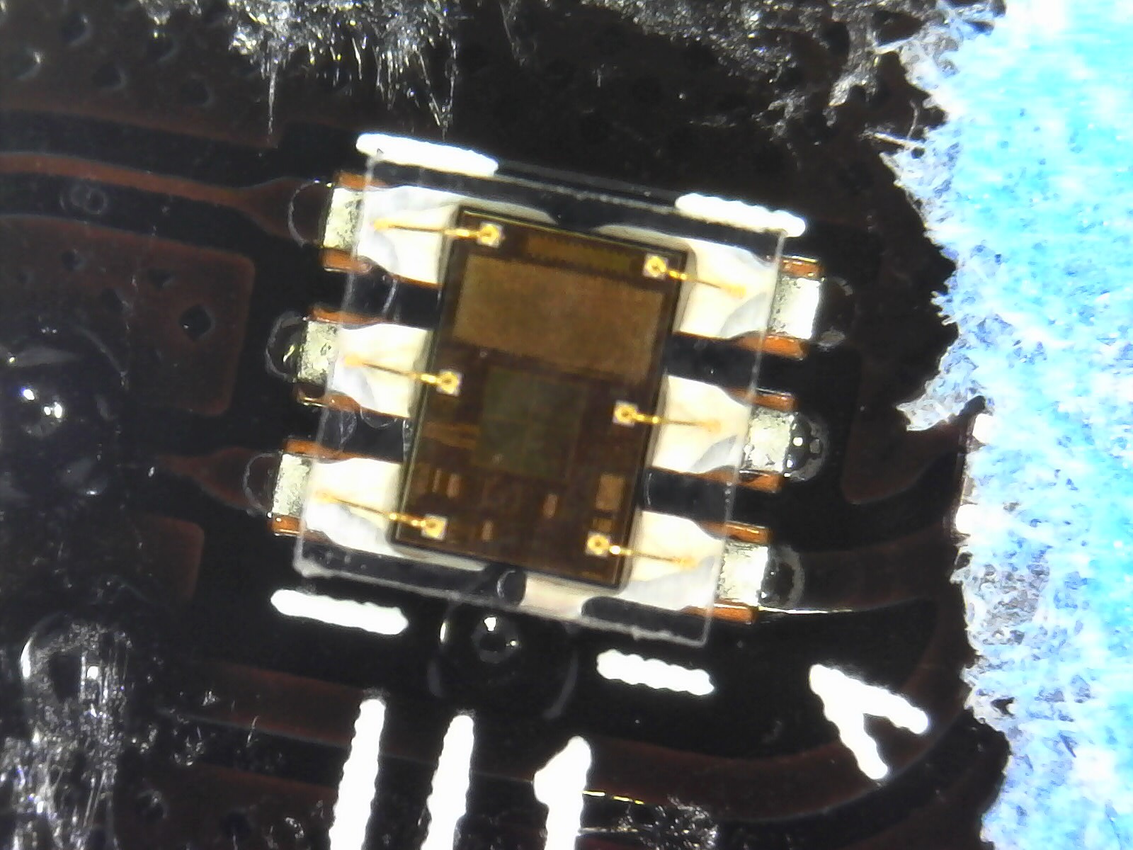
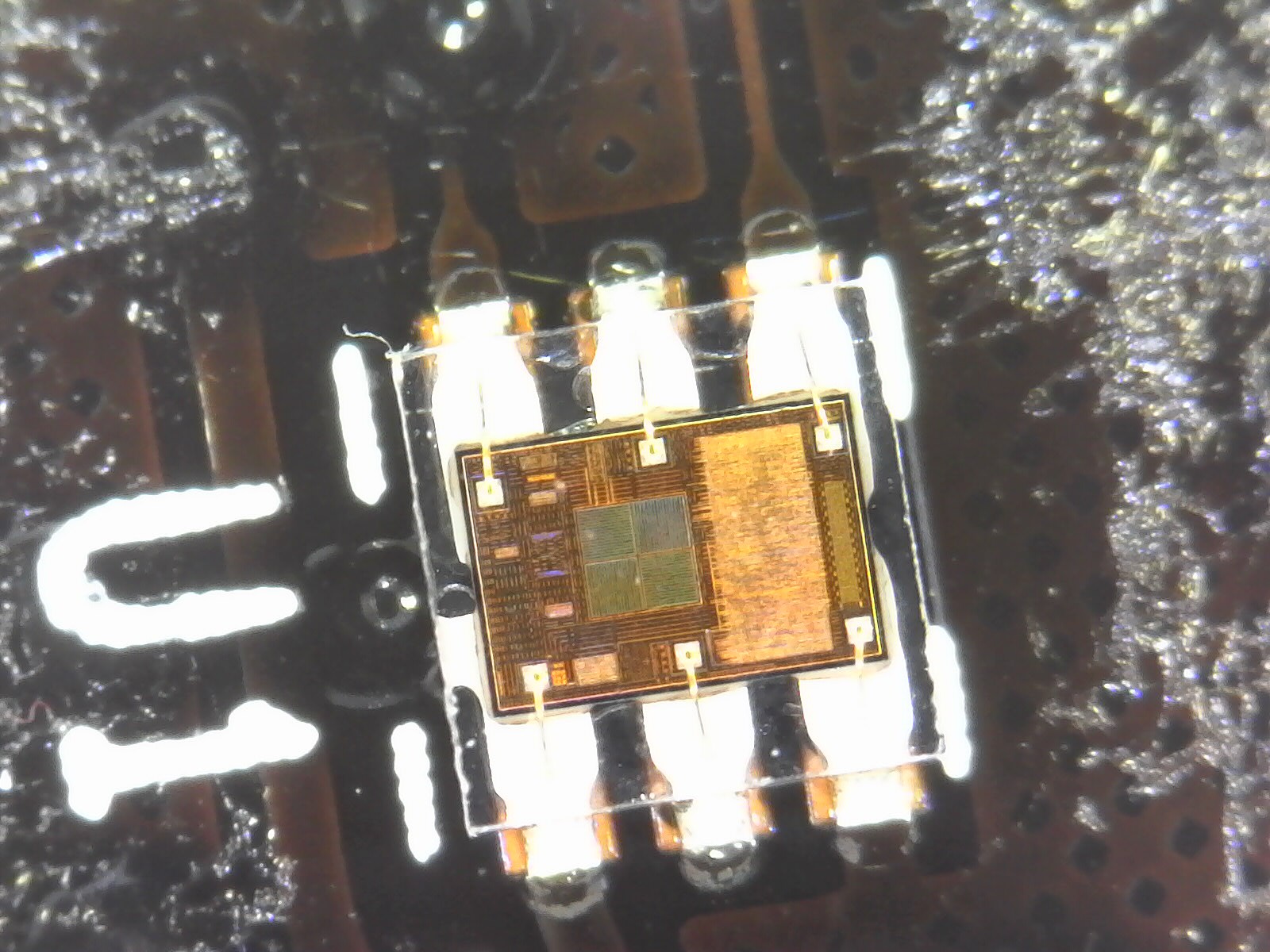
Maybe it's some other chip. Let's see how many other 6-pin I2C light sensors that support 3.0V power exist on Digikey. 124? We're going to need more information. I decided to pull the flex PCB off my display to get a higher-resolution photo of the IC itself.
![]()
A photo taken with my USB microscope, showing the ambient light sensor IC. This is actually surprisingly helpful. We can see the bond wires and the patterns on the IC, which we can try to match against the Digi-Key photos.
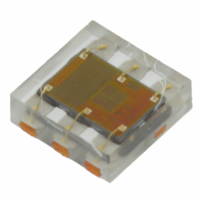
The TSL2561 looks promising, but we know that the Adafruit library for it doesn't work:
![]()
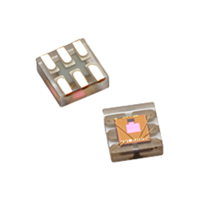
The TSL2561 photo on Digi-Key. This is also the same photo they use for the TSL2571. Other manufacturers look different:
![]()
The APDS-9306-063 has the bond wires going to the wrong place. ![]()
Wrong bond wires again on the VEML6035, plus the black background. Based on this, I'm assuming it's another chip from ams-OSRAM, in the same family as the TSL2561.
Adafruit also has a driver for the TSL2591, since they sell that breakout board too. Let's try that?
meatmanek@pi4:~ $ cat > tsl2591.py
# adapted from https://learn.adafruit.com/adafruit-tsl2591/python-circuitpython
import board
import adafruit_tsl2591
i2c = board.I2C()
sensor = adafruit_tsl2591.TSL2591(i2c, address=0x39)

print('Light: {0}lux'.format(sensor.lux))
print('Visible: {0}'.format(sensor.visible))
print('Infrared: {0}'.format(sensor.infrared))

meatmanek@pi4:~ $ . venv/bin/activate
(venv) meatmanek@pi4:~ $ python ./tsl2591.py
Traceback (most recent call last):
  File "/home/meatmanek/./tsl2591.py", line 2, in
    import adafruit_tsl2591
ModuleNotFoundError: No module named 'adafruit_tsl2591'

(venv) meatmanek@pi4:~ $ pip3 install adafruit-circuitpython-tsl2591
Looking in indexes: https://pypi.org/simple, https://www.piwheels.org/simple
...
Successfully installed adafruit-circuitpython-tsl2591-1.3.12
(venv) meatmanek@pi4:~ $ python ./tsl2591.py
Traceback (most recent call last):
  File "/home/meatmanek/./tsl2591.py", line 4, in
    sensor = adafruit_tsl2591.TSL2591(i2c, address=0x39)
             ^^^^^^^^^^^^^^^^^^^^^^^^^^^^^^^^^^^^^^^^^^^
  File "/home/meatmanek/venv/lib/python3.11/site-packages/adafruit_tsl2591.py", line 132, in __init__
    raise RuntimeError("Failed to find TSL2591, check wiring!")
RuntimeError: Failed to find TSL2591, check wiring!
Looking at line 132 in adafruit_tsl2591.py, it looks like it's also checking a register to see if the chip has the right device ID:
    def __init__(self, i2c: I2C, address: int = _TSL2591_ADDR) -> None:
        ...
        # Verify the chip ID.
        if self._read_u8(_TSL2591_REGISTER_DEVICE_ID) != 0x50:
            raise RuntimeError("Failed to find TSL2591, check wiring!")
        ...
At this point I start looking through the Linux drivers for TSL* light sensor ICs:
meatmanek@brix1:~/raspberrypi-linux$ (ccache arm64) git grep -i ,tsl Documentation/
Documentation/devicetree/bindings/iio/light/amstaos,tsl2563.yaml:$id: http://devicetree.org/schemas/iio/light/amstaos,tsl2563.yaml#
Documentation/devicetree/bindings/iio/light/amstaos,tsl2563.yaml:      - amstaos,tsl2560
Documentation/devicetree/bindings/iio/light/amstaos,tsl2563.yaml:      - amstaos,tsl2561
Documentation/devicetree/bindings/iio/light/amstaos,tsl2563.yaml:      - amstaos,tsl2562
Documentation/devicetree/bindings/iio/light/amstaos,tsl2563.yaml:      - amstaos,tsl2563
Documentation/devicetree/bindings/iio/light/amstaos,tsl2563.yaml:        compatible = "amstaos,tsl2563";
Documentation/devicetree/bindings/iio/light/amstaos,tsl2591.yaml:$id: http://devicetree.org/schemas/iio/light/amstaos,tsl2591.yaml#
Documentation/devicetree/bindings/iio/light/amstaos,tsl2591.yaml:    const: amstaos,tsl2591
Documentation/devicetree/bindings/iio/light/amstaos,tsl2591.yaml:            compatible = "amstaos,tsl2591";
Documentation/devicetree/bindings/iio/light/tsl2583.yaml:      - amstaos,tsl2580
Documentation/devicetree/bindings/iio/light/tsl2583.yaml:      - amstaos,tsl2581
Documentation/devicetree/bindings/iio/light/tsl2583.yaml:      - amstaos,tsl2583
Documentation/devicetree/bindings/iio/light/tsl2583.yaml:                compatible = "amstaos,tsl2581";
Documentation/devicetree/bindings/iio/light/tsl2772.yaml:      - amstaos,tsl2571
Documentation/devicetree/bindings/iio/light/tsl2772.yaml:      - amstaos,tsl2671
Documentation/devicetree/bindings/iio/light/tsl2772.yaml:      - amstaos,tsl2771
Documentation/devicetree/bindings/iio/light/tsl2772.yaml:      - amstaos,tsl2572
Documentation/devicetree/bindings/iio/light/tsl2772.yaml:      - amstaos,tsl2672
Documentation/devicetree/bindings/iio/light/tsl2772.yaml:      - amstaos,tsl2772
Documentation/devicetree/bindings/iio/light/tsl2772.yaml:                compatible = "amstaos,tsl2772";
Documentation/devicetree/bindings/spi/cdns,qspi-nor.yaml:      cdns,tslch-ns:
Documentation/devicetree/bindings/trivial-devices.yaml:          - taos,tsl2550
Looks like there are 4 distinct drivers, some handling multiple chips. We've already eliminated the tsl2561 (handled by the tsl2563 driver) and the tsl2591 (handled by its own driver), let's try the tsl2571 (handled by the tsl2772 driver). I create this device tree overlay file:
#include <dt-bindings/interrupt-controller/irq.h>

/dts-v1/;
/plugin/;

/ {
    compatible = "brcm,bcm2835";

    fragment@0 {
        target = <&i2c1>;
        __overlay__ {
            #address-cells = <1>;
            #size-cells = <0>;
            status = "okay";

            als@39 {
                    compatible = "amstaos,tsl2571";
                    reg = <0x39>;
            };
        };
    };
};
This should get the tsl2772 driver loaded and configured to talk to a tsl2571 on i2c bus 1, address 0x39.
When loading this dtoverlay file, I get an error:
meatmanek@pi4:~ $ sudo dtoverlay pipad-als
meatmanek@pi4:~ $ dmesg | grep tsl
[   61.915038] tsl2772 1-0039: supply vdd not found, using dummy regulator
[   61.916654] tsl2772 1-0039: supply vddio not found, using dummy regulator
[   61.943592] tsl2772 1-0039: tsl2772_probe: i2c device found does not match expected id
[   61.943846] tsl2772: probe of 1-0039 failed with error -22
Looks like more of the same problems. I patched the code to print out the ID it found (0x93). Looking at the code in this driver that checks the chip ID, none of the chips supported by this driver would have ID 0x93 -- it only supports 0x0*, 0x2*, and 0x3*:
/* Use the default register values to identify the Taos device */
static int tsl2772_device_id_verif(int id, int target)
{
    switch (target) {
    case tsl2571:
    case tsl2671:
    case tsl2771:
        return (id & 0xf0) == TRITON_ID;
    case tmd2671:
    case tmd2771:
        return (id & 0xf0) == HALIBUT_ID;
    case tsl2572:
    case tsl2672:
    case tmd2672:
    case tsl2772:
    case tmd2772:
    case apds9930:
        return (id & 0xf0) == SWORDFISH_ID;
    }

    return -EINVAL;
}
Around this time I decided to see if I could get a better photo of the IC:
![]()
Quite a bit clearer.
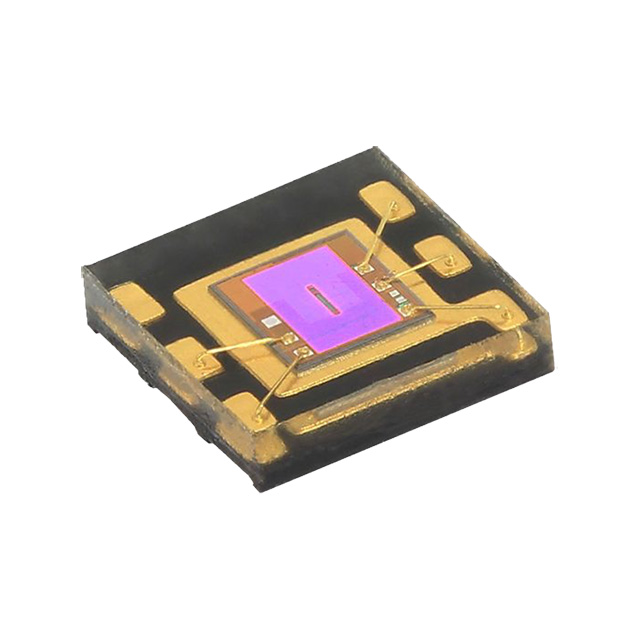
Back to the search -- if we've tried the 2561, 2571, and 2591, maybe it's the 2581? I google for tsl2581 and this image pops up:
![]()
That looks extremely close (closer than the 2561/2571 image does), let's give it a try. Just a 1-character change to my device tree overlay file, and:
meatmanek@pi4:~ $ sudo dtoverlay pipad-als
meatmanek@pi4:~ $ dmesg | grep tsl
[  181.899420] tsl2583 1-0039: Light sensor found.
Well, that's encouraging!
Since this is an iio driver, the sysfs files live in a directory under /sys/bus/iio/devices:
meatmanek@pi4:~ $ cd /sys/bus/iio/devices/iio\:device0/
meatmanek@pi4:/sys/bus/iio/devices/iio:device0 $ ls
in_illuminance_both_raw   in_illuminance_calibscale            in_illuminance_input_target                in_illuminance_ir_raw     of_node    uevent
in_illuminance_calibbias  in_illuminance_calibscale_available  in_illuminance_integration_time            in_illuminance_lux_table  power
in_illuminance_calibrate  in_illuminance_input                 in_illuminance_integration_time_available  name                      subsystem
meatmanek@pi4:/sys/bus/iio/devices/iio:device0 $ cat in_illuminance_ir_raw
0
meatmanek@pi4:/sys/bus/iio/devices/iio:device0 $ cat in_illuminance_both_raw
0
Turns out that once you read in_illuminance_input, then in_illuminance_ir_raw and in_illuminance_both_raw will have nonzero values:
meatmanek@pi4:/sys/bus/iio/devices/iio:device0 $ cat in_illuminance_input
0
meatmanek@pi4:/sys/bus/iio/devices/iio:device0 $ cat in_illuminance_ir_raw
130
meatmanek@pi4:/sys/bus/iio/devices/iio:device0 $ cat in_illuminance_both_raw
1025
Success! Hopefully this is actually the right chip, and not just something that happens to have a similar register map. It does seem to respond to changes in brightness, and can even tell the difference between an incandescent light and LED lights:
# Under incandescent light:
meatmanek@pi4:/sys/bus/iio/devices/iio:device0 $ grep ^ in_illuminance_*_raw
in_illuminance_both_raw:677
in_illuminance_ir_raw:133

# Under white LED light, dimmed to give a similar "both" value:
meatmanek@pi4:/sys/bus/iio/devices/iio:device0 $ grep ^ in_illuminance_*_raw
in_illuminance_both_raw:687
in_illuminance_ir_raw:87
Now I just need to get this thing re-adhered to the back of the LCD without looking too ugly.
-
Audio codec: ground-centered mode, BCLK, headset detection
01/21/2024 at 08:23 • 6 commentsI haven't worked on the audio codec part of my board in a while (I don't think I ever tested it on rev1), but it's the last major section of my rev2 PCB that needs testing. A codec is a coder/decoder -- something that encodes and decodes a digital signal --- in this case, to/from analog, so it's an ADC and DAC. In PC terminology, this would be the sound card.
The desired feature set is:
- Stereo headphone output
- Stereo speaker output
- Stereo line output (through the 30-pin connector)
- Headset microphone input (i.e. TRRS headphones that you'd use with a phone)
- The iPad's built-in microphone
- Headset detection (able to determine whether a pair of headphones is inserted into the jack, and ideally whether it includes a microphone or not)
My original design used a TLV320AIC3104 codec from TI. This has a built-in headphone amplifier, headset detection, and enough other inputs+outputs to generally fit my needs. However, this codec has one problem that made it a poor choice: it doesn't have "ground-centered" outputs.
Ground-centered outputs?
Generally speaking, most ICs can't produce voltages lower than their negative supply voltage (which is usually GND) and their positive supply voltage. A lot of audio codecs will avoid negative voltages by centering their output voltage at some voltage between the power supply and ground. However, most headphones don't really like having a DC offset in the audio signal being pumped into them. Any DC offset will simply result in a steady flow of power through your headphones' speaker coils, which gets wasted as heat. It also means you get a loud pop sound from your headphones whenever your codec turns on its outputs or when you plug in your headphones.
There are a few options to deal with this:
The easiest is to just insert DC-blocking capacitors between the output of your codec and the jack. This forms (along with whatever device you plug into the jack) an RC or RLC circuit. This creates a trade-off between capacitor size and your bass response. For typical 32-ohm headphones, in order to have the cutoff frequency be above 50Hz, you'd need approximately 100 μF of capacitance per channel. If you want to get down to 20Hz, you'd need 250 μF. That much capacitance is going to take up a nontrivial amount of space (and height) on the board. The frequency response will change depending on the impedance of whatever you plug into it, making it hard to compensate for.
The next option is called "pseudo-differential" output. In this mode, you make the ground pin of your audio connector (the sleeve in your TRS connector) not actually match your circuit board's ground, but drive it with some voltage above ground. In the simplest form, this could just be some constant DC offset, and each channel can be driven above or below that offset. If you want to increase the maximum peak-to-peak voltage range, you can pull your ground pin low when your audio signal goes high, or pull your ground pin high when your audio signal goes low, same as how an H-bridge works. (This gets a little more complicated with stereo signals.)
Pseudo-differential outputs should give you a nice flat frequency response, but sometimes they're infeasible. If you connect your audio ground (which your codec is trying to drive to, say, VCC/2) to your system ground (0V), you now have a short circuit. This isn't usually a problem with headphones, but if you were to e.g. plug your device into the aux jack of your car (which might connect the audio ground to the car's ground) while also charging your device from the car's USB port (which might connect the USB port ground to the car's ground), you'd end up with a short circuit.
The nicest option is to have your signals be ground-centered -- that is, they have an average voltage of 0, and the signal goes both positive and negative. This is more complicated because you need some way to generate a negative voltage supply, and your headphone driver needs to be able to take a non-ground-centered input and shift it down to ground for its output.
Fortunately, there are audio codecs that can provide ground-centered outputs with minimal extra circuitry required. I picked the TLV320AIC3206 from TI --- partly because it's similar to the 3104 that I had originally used, partly because TI's documentation is much more accessible to hobbyists than most other manufacturers, partly because I knew it had a Linux driver.
This chip can generate a negative voltage supply by using a charge pump architecture, only requiring two external capacitors. It can then use that negative voltage to provide ground-centered headphone outputs. (But not on its line out pins, unfortunately. Not as big of a problem, as line-level inputs are usually assumed to be high-impedance, so we can use relatively small DC-blocking capacitors.)
To enable ground-centered headphone outputs in the 3206, we just need to set one register. The Linux driver for this family of codecs was written for the 3204 (which doesn't support ground-centered output) and didn't support configuring that register, but it was an easy enough thing to patch.
I was getting really strange behavior when the ground-centered mode was enabled. Loud clicking (low-frequency square wave oscillations), no output at all, etc. Eventually I realized that I had not grounded my GND_SENSE pin. This is supposed to be grounded somewhere near the headphone jack, but I had left it floating. Once I grounded that trace, everything worked properly.
Clock sources: oh no, do I need a crystal oscillator?
I've told this story a little out of order -- Before I could worry about the ground-centered outputs, I needed to get the aic3206 to make sound at all.
All audio codecs need some sort of frequency reference, so that they output samples at a steady rate. The TLV320AIC3206 is very flexible about how you can provide that: The datasheet says:
The required internal clock of the TLV320AIC3206 can be derived from multiple sources, including the MCLK pin,
the BCLK pin, the GPIO pin or the output of the internal PLL, where the input to the PLL again can be derived
from the MCLK pin, the BCLK or GPIO pins. Although using the PLL ensures the availability of a suitable clock
signal, PLL use is not recommended for the lowest power settings. The PLL is highly programmable and can
accept available input clocks in the range of 512 kHz to 50 MHz.I designed my board assuming that I'd just use BCLK, which is the bit clock of the I2S bus that is transferring the digital audio data between the codec and the CPU. Whenever there's audio output or input, the Raspberry Pi should be driving this clock line anyway (it's necessary for the data transfer). I left the MCLK pin floating (with a test point).
However, when initially trying to bring up the codec, I discovered that the driver requires you to pass a clock designator as the "mclk" input, and actually exits with an error if you don't specify an "mclk" clock. I could see that there was code in the driver that theoretically could set the correct registers in the codec to use BCLK as the input to the PLL, but I couldn't see anywhere that it was being called. Without the clocks properly configured, the codec won't be able to generate any audio. I reached out to the author of the clock-handling code in the aic32x4 driver to ask for guidance.
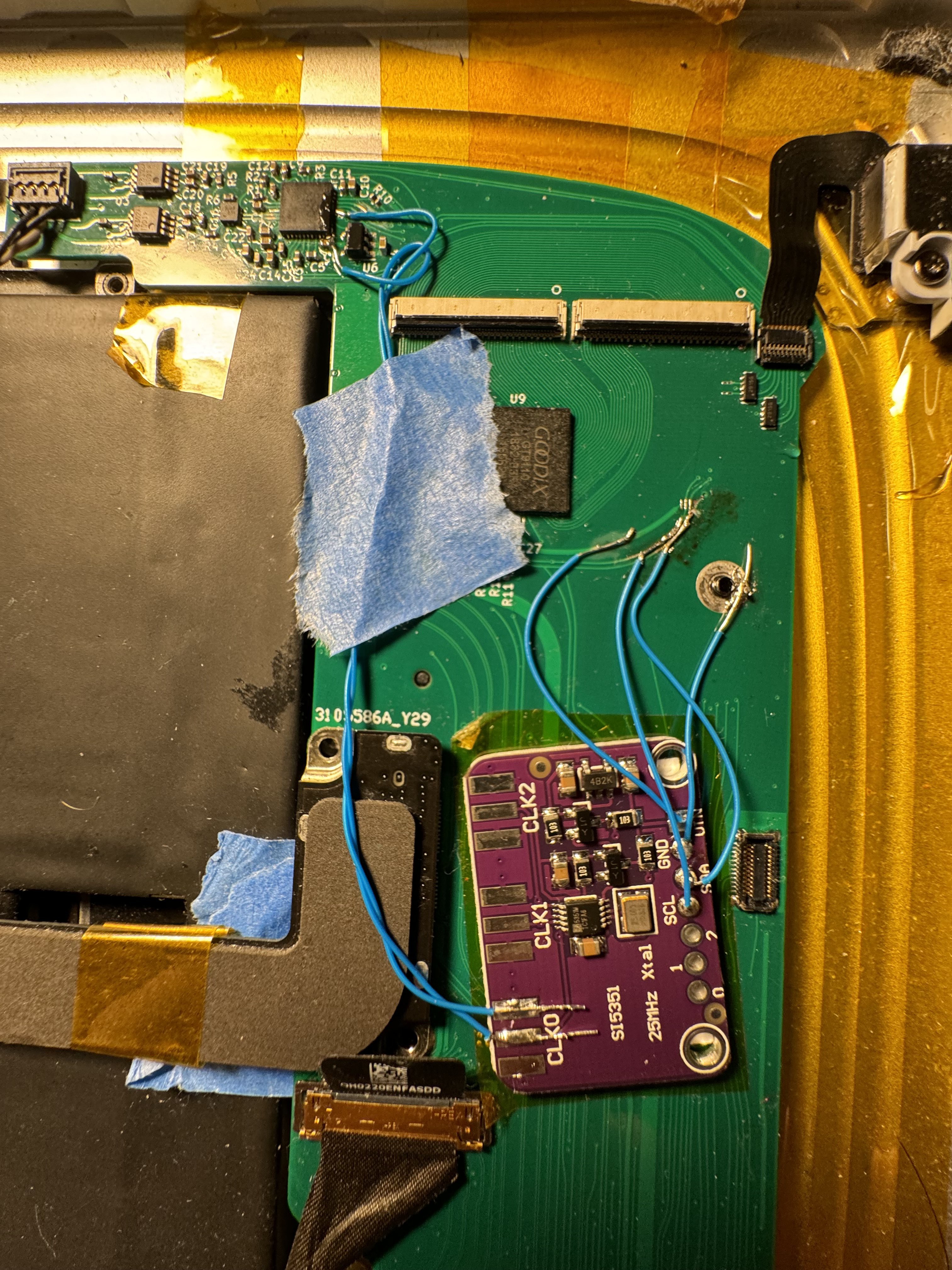
Meanwhile, I took a Si5351 clock generator board that I had lying around (a random AliExpress purchase a while ago), bodged it into the board such that its output was connected to the codec's MCLK pin, and figured out how to get it set up in my device tree such that the aic32x4 driver understood that the Si5351 was connected to MCLK. Once I had this in place, the codec worked perfectly.
![]()
SI5351 acting as MCLK for my audio codec. At some point, I figured out that I could short MCLK and BCLK, which would allow the codec to work the way the Linux driver configures it without the Si5351 or any other external clock.
With the help of the driver developer that I had contacted, I figured out enough about how clocks are supposed to work in the kernel to write a patch that allows me to configure the PLL to use BCLK as input, by setting this in my device tree overlay:
            tlv320aic3206: tlv320aic3206@18 {
...
                clocks = <&clocks BCM2835_CLOCK_PCM>;
                clock-names = "bclk";
...
            };
Fantastic, now I don't need any bodges for the clocks to work (just the one so that ground-centered mode works).
Headset detection
You know how your computer and phone (back when they had 3.5mm jacks, at least) will mute their speakers whenever you plug in headphones? I'd really like that same functionality on my board. In order to make this work, I need to detect whether headphones are plugged into the jack, a process creatively named "headset detection".
Some 3.5mm jacks provide a pin that acts as a switch to let you know that something is inserted, but this gives you just one bit of information. In my case, I need at least two, maybe 3 bits:
- Are there headphones plugged in?
- Do the headphones have a microphone?
- (Optionally) Are the headphones stereo?
The aic3206 can answer the first two questions without any special switches in the headphone jack, just the 4 TRRS connections. This would be convenient.
Like the ground-centered mode, though, the existing Linux driver doesn't have the ability to configure the register in the aic3206 that controls headset detection. This was an easy enough patch.
Once I enabled this, however, I had an annoying ~2kHz tone in my headphones; it was a lot worse when the plug was only partly plugged in. Some headphones were worse than others, but it was audible in all of the headphones I tested.
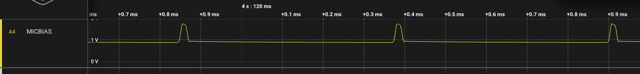
I noticed that the MICBIAS pin from the codec had a ~15 microsecond pulse every ~500 microseconds; there's a resistor connected between this pin and the sleeve of my headphone jack, meant to bias the microphone in the headphones. Theoretically, I shouldn't be able to hear this --- it should go through the microphone and back to ground --- but I think there's enough cross-talk between traces (or wires in my headphone cable) that it's audible.
![]()
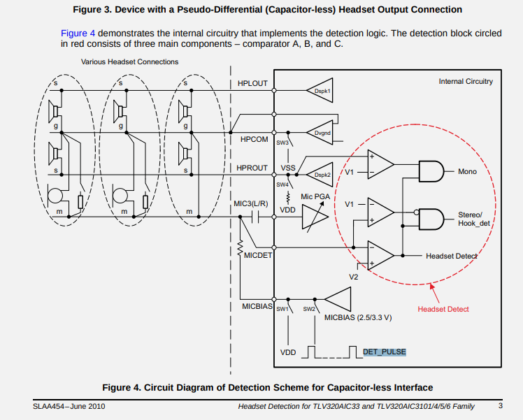
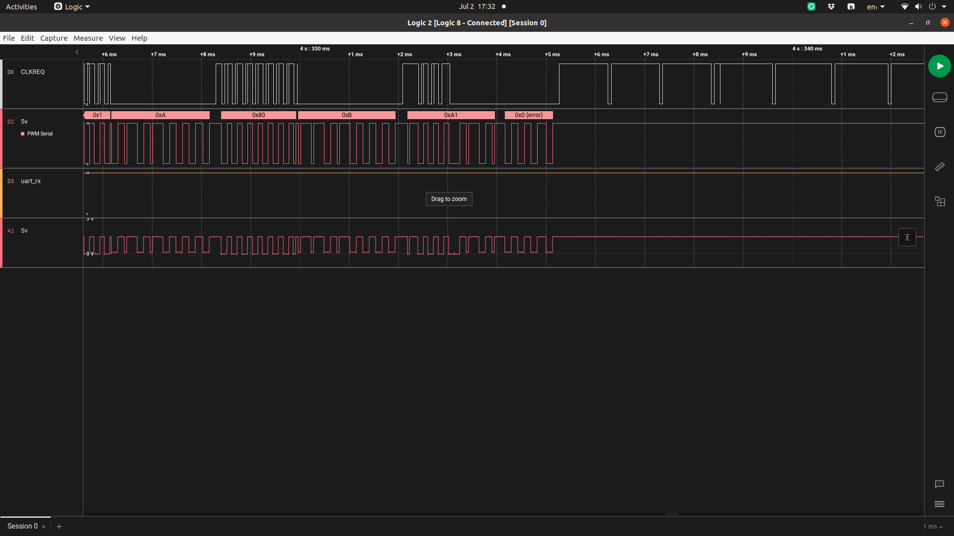
On the TI forums, I learned that the aic3206 headset detection works similarly to the aic3104 headset detection. The latter has an application note describing its functionality. From the app note, we can see that this pulse train is expected when headset detection is enabled:
![]()
![]()
Lovely. I've asked for tips on the TI forum about avoiding this audible squeal, but since I don't see any configuration registers that would change this behavior, I'm not sure there's much to do other than avoid having headset detection enabled in the chip for very long.
The 3.5mm jack in the iPad does have a "DETECT" pin, which I had only pulled out to a test pad, as I assumed that I could rely on the codec's built-in headset detection. This pin seems to be connected to the left audio channel when nothing is inserted, and, as far as I can tell, goes open when something is inserted. Perhaps I can connect this to a GPIO pin with a pull-up resistor, and when this goes high (indicating something has been plugged in) briefly enable the codec's headset detection to determine whether the headphones have a microphone or not.
-
It's a tablet! (Rev2 PCB testing)
12/30/2023 at 05:04 • 1 commentIt works!
I ordered the second revision of my PCB a few months back, and have been slowly working my way through testing and debugging the functionality. So far, the PCB hasn't required any modifications -- all the issues I've encountered have been soldering or software issues.
A brief list of things I tested / debugged:
- PCIe port (for the NVMe drive) worked without issue.
- 5V boost converter mysteriously stopped working -- the 787k resistor turned into a 150k resistor?? Maybe I just placed the wrong resistor there in the first place, but I swear this was working before. (I use a 787k and 150k resistor as a feedback network for the MP3422GG boost converter.) Replacing the resistor fixed the issue.
- Battery charger wasn't charging, until I discovered some passives were missing. Replacing them fixed the issue.
- LCD backlight controller wasn't working, until I noticed that the inductor had a bad solder joint. Touching that up with a soldering iron fixed the issue.
- The image on the LCD was corrupted -- at first, it was showing 3-ish copies of the screen vertically, like it was skipping all but every 3rd line. After messing with timings and frequencies for a while, I noticed that pressure on the board would change the severity of the problem (see youtube video below). At some point, the problem got significantly better, where the screen would be relatively stable vertically, but individual lines would be corrupted at some point. (Unfortunately, forgot to get a photo of this.) I noticed that it would improve when I cranked up the LVDS differential output voltage on the sn65dsi83 (CHA_LVDS_VOD_SWING in the datasheet). This indicated to me that there was an analog problem on the board. Hitting the sn65 and the LVDS connector with some flux and hot air solved the issue.
- A while later, I noticed that my battery voltage was really low, and that it wasn't pulling any current from the USB power supply. After looking for any error codes or anything weird in the i2c registers of the battery charger IC, I bodged an LED and resistor onto the STAT pin of my charger IC, and that glowed solid. If there were a fault code, it would've blinked at 1Hz. Once again, flux and hot air solved the issue.
- I tested the touchscreen - clean (none of the noise that plagued my earlier board revision; dunno why this is any better, as the only change I made to this part of the hardware was rounding the tracks to look pretty), but had a dead zone on the middle few Y lines. More flux and hot air fixed that.
I'm beginning to think that my bismuth-based low temperature solder is a bad idea, especially since the 0.8mm PCB is so flexible.
Anyway, with all those issues worked through, I decided to assemble the whole thing into tablet form (removing the battery wires I had soldered into place for testing purposes) and take a little victory lap.
Next steps
There's still a few more bits of hardware to test:
- The soundcard (this is probably the next thing on the agenda)
- SDIO communication with the battery
- At some point I really need to see if I can talk to the ambient light sensor + compass; I've been wiring up that connector on every board rev and never done anything with it.
- I think/hope the compass has an accelerometer as well, which would let me automatically change the screen orientation as I rotate the tablet.
There's also a bunch of stuff I'd like to do with the dock connector:
- See if I can support USB peripherals through the "Camera connector" dongle
- Support the iPad Keyboard Dock
- Test component video output
- I'd really like to get the iPad's own Wifi/BT radio working (this is actually mounted on the PCB that connects the logic board to the dock connector.)
Also, Raspberry Pi OS's GUI is barely functional on a tablet:
- You can pull up an on-screen keyboard through the menu, but it only supports letters, space, enter, and backspace? No numbers, symbols, modifier keys (it can type uppercase letters though), autocorrect, etc.
- The on-screen keyboard doesn't appear automatically.
- The UI is clearly meant for a mouse; all the buttons are too small to be effective tap targets.
I'd like to play around with Ubuntu Touch / UBPorts and/or Android. These should provide a much more usable interface.
Some other software improvements to make:
- Make sure the battery status (percentage, charging/discharging) shows up in the UI
- Get the volume buttons, orientation lock, and home button (front button) working.
- Convince the OS to hibernate instead of shut down when I press the lock button. Maybe if you press the button for >2s, have it pull up a power menu?
Finally, I'll probably need to do another board revision to get the case to close entirely:
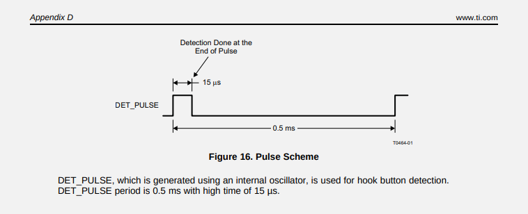
![]()
The case can't close properly because the PCB assembly ends up being too thick with the CM4. I might end up having to make parts of the board out of flex PCB. Basically, the CM4 and its connectors make the board about as thick as it can be and still fit in the case, but the CM4 is on the bottom, and I need some parts on top of the board fairly close to the CM4. If the board were flexible, this might just work.
![]()
See how the right side sticks up a bit? That'd be fine, except that the middle needs to be low so that the dock connector PCB (grey strip up the middle) isn't too high. The LVDS connector is a bit of a problem too. -
NVMe, HDQ, SDIO, and curvy PCB traces
10/04/2023 at 07:15 • 4 commentsI apologize for the long delay since the last update. I'm still here, making spurts of progress here and there.
Since the last log, I've worked on a number of things:
- Figuring out why NVMe / PCIe wasn't working
- Successfully getting the Pi to talk to the battery pack through TI's HDQ protocol.
- Unsuccessfully attempting to get the Pi to talk to the iPad's Wifi chip through SDIO.
- Redesigning the PCB to fix some earlier issues.
NVMe
On my previous revision of the PCB, I had added a M.2 slot to allow for a 2230-sized NVMe SSD -- these are getting pretty cheap these days (around $15 for 128GB), and should be faster and more durable than eMMC.
When I tested this slot by putting an SSD in it, I couldn't see anything with lspci, etc. I tried observing with my oscilloscope and didn't see anything happening, but PCIe is a little beyond the bandwidth of my scope.
Fortunately, around this time, Arya Voronova was publishing her PCIe for Hackers series on Hackaday, and a line in this article caught my attention:
As you might expect, RX on one end connects to TX on another end, and vice-versa – it’s just like UART, but spicy.
Had I gotten TX and RX wrong? Sure enough, I had. The schematic symbol I used for the M.2 slot was labeled from the perspective of the card, not the host, so I had wired the host's TX line to the card's TX line. Don't trust random symbols — check the datasheet!
I designed a little interposer board that fits in the M.2 slot, swaps TX and RX, and has another M.2 slot on top where you can put the SSD. This (and some reflow of a few bad solder joints, a perennial problem with this project) fixed the issue and got NVMe working perfectly.
The interposer board is too big to fit inside the iPad case, but it let me verify the fix before ordering and assembling a whole new board revision.
SWI? HDQ? 1-Wire?
The iPad's battery connector has a pin named BATT_SWI_CONN_R, which is used for serial communication between the processor and the battery. From what I discovered in online research, Apple devices from this era all used TI battery controller chips which speak the HDQ protocol, a proprietary single-wire interface that only seems to show up on these TI battery controllers. For reasons, Apple decided to rename this "SWI" (presumably, "single-wire interface") rather than just calling it HDQ.
I wanted to make sure I could get the Pi talking to the battery with just a trace wired between a GPIO pin and the battery's SWI pad. If I needed extra hardware to make this communication work, it would be nice to know before ordering a board revision.
First things first, I wanted to double check that the battery actually spoke HDQ, so I flashed this Arduino sketch from mozzwald onto an Arduino Uno and hooked it up. This worked perfectly:
iPhone 4G Battery Detected
Device: bq27541
Firmware: v1.25
Hardware: 0xB5
Remaining Capacity: 1166 mAH
Full Charge Capacity: 6264 mAH
Design Capacity: 6500 mAH
Time to empty: N/A, not discharging
Time to full: N/A, not charging
State of Charge: 19%
Battery Voltage: 3.73V (3730mV)
Temperature: 24.00�C / 75.38�F / 2971 raw
Charge Cycle Count: 146 times
(Looks like the battery thinks it's full-charge capacity is 96% what it was when it was new. Pretty good for a 13-year-old battery!)
Moving back to Pi land, I hooked up some jumper wires between a Pi 4 and the battery's ground / SWI contacts, and set about trying to get the Pi to speak HDQ.
In the Linux kernel, there's a driver called bq27xxx_battery_hdq, which sounds perfect -- I want to talk to a BQ27541 over HDQ. However, it turns out that this uses the Linux kernel's 1wire subsystem. HDQ and 1wire aren't actually compatible -- they're close enough at the physical layer that TI made their OMAP processors capable of speaking either, and the Linux driver for this hardware can set it into HDQ mode. This isn't helpful for me, though, since the Pi doesn't use an OMAP processor.
However, there's a w1-gpio implementation which can use an arbitrary GPIO pin to implement 1wire. (Within the linux kernel, the shorthand used for 1wire is w1, presumably because you can't start C identifiers with a number.). I set about patching this to speak HDQ well enough for the bq27xxx_battery_hdq driver. It didn't immediately work -- some transactions would work okay, but some would fail.
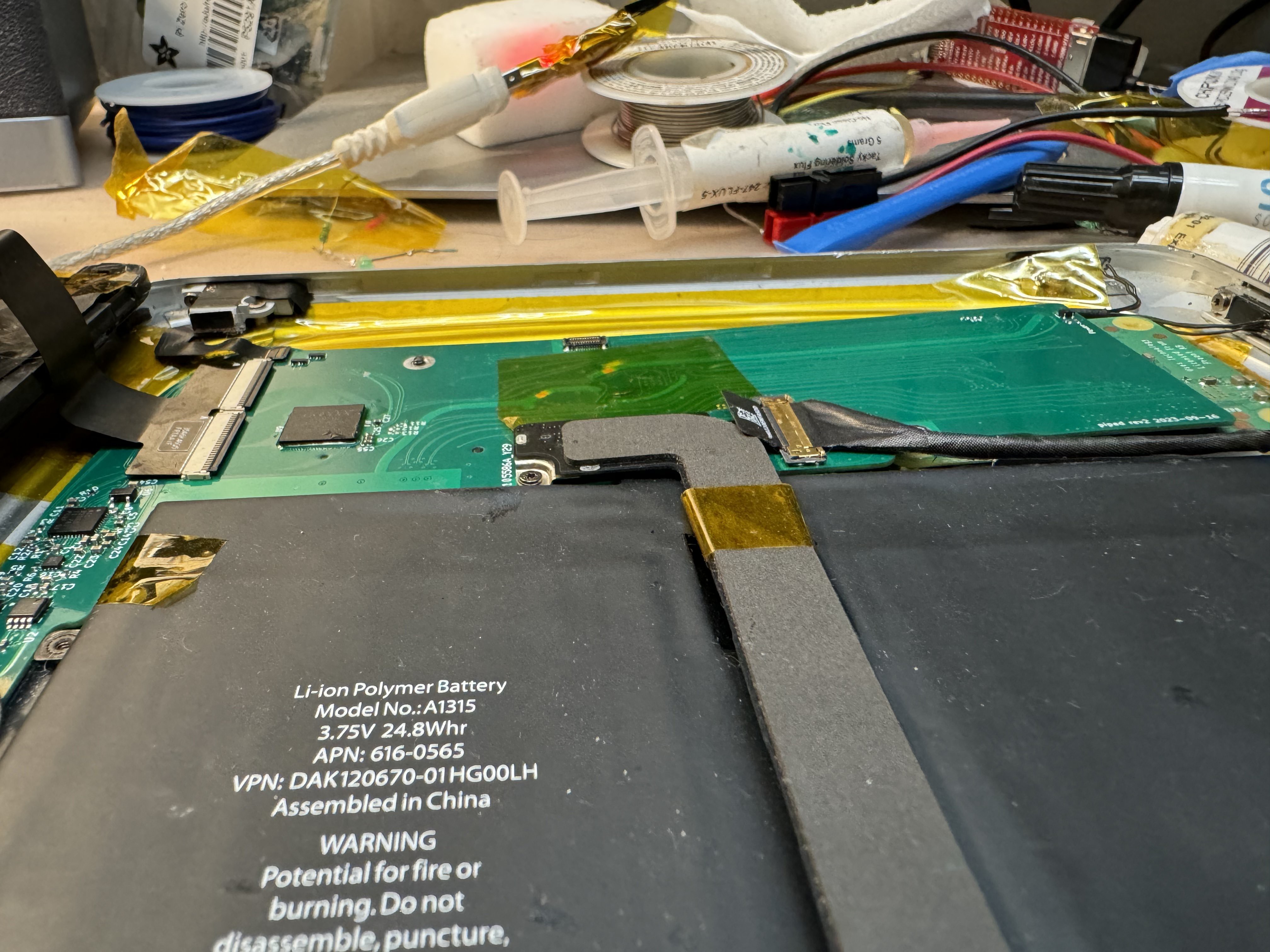
To help figure out what it was doing wrong (and as an interesting diversion), I ended up also writing a Saleae plugin for decoding HDQ (or, really, any serial protocol that encodes 0s and 1s as short/long pulses). This was helpful in diagnosing issues, especially when I started toggling a different GPIO pin during different sections of my patched w1-gpio code so I could follow along with the execution of my driver code.
![]()
ignore the pin names on the left side of the screen -- sometimes I'm too lazy to update these. A low-valued series resistor between the battery and the GPIO pin makes it so the bq27541 can't quite pull the voltage all the way down to zero. This helped me identify which device was transmitting at any given time. The code isn't pretty (definitely not going to get merged into the mainline kernel in this state), and it almost won't speak 1Wire anymore, but I have a driver that works!
Why won't the BCM4329 respond on SDIO?
The iPad's BCM4329 wifi/bluetooth controller is not on its logic board, it's on a skinny PCB that runs down the middle of the iPad from the logic board at the top to the 30-pin connector at the bottom. It would be convenient to be able to use this, rather than the CM4's wifi, because it's already in the right place for the iPad's antenna connectors. If I were to use a wifi CM4, I'd need to find an antenna extension cable / splitter to go from the CM4's single antenna port to the iPad's two antennas (or pick one and deal with poor reception if the iPad is facing the wrong way).
Using a breakout board I designed ages ago, I hooked up this PCB to the CM4IO with jumper wires. (I'm using the CM4 and CM4IO for this testing, rather than a Pi 4, because I think the SDIO is 1.8V, and you can change the IO voltage of the CM4 to 1.8V rather than needing a bunch of level shifters.)
As usual, I've written a device tree overlay for the BCM4329, and I can see that the CM4 is attempting to send messages on the SDIO bus, but getting no response. As this excellent SiLabs article explains,
Before using a Wi-Fi part connected to the SDIO bus of a Linux system, it is necessary that the system detects the HW on the bus.
When detection succeeds, the kernel has retrieved the VID/PID for the device.
Looking for a driver matching the VID/PID is only possible if the VID/PID has been retrieved from the device.- As as consequence, device tree changes related to your device have no effect until SDIO detection is OK.
Once I can get the wifi controller to respond at all, we should be able to make some more progress.
I assume one of two things is wrong:
- I'm doing something silly with the enable, wake, or power pins for the BCM4329
- I've already fried the BCM4329 somehow and it'll never respond
I probably ought to put the original iPad parts back in and see if wifi still works.
Having too much fun with Kicad's "Fillet Tracks" tool
![]()
Seriously. Too much fun. I don't think I left a single track un-filleted ![]()
Electrons hate corners, right? This version of the PCB fixes a few issues: the PCIe TX/RX issues mentioned above, the power switch logic, the LCD backlight driver, and certainly some other things I'm forgetting now.
I also added a trace for the HDQ pin, but didn't route traces for SDIO. I did include some tiny test pads on the board in case I want to connect SDIO later.
I've submitted my PCB order, so I expect in the next few days I'll notice some silly mistake I made in the design, or some essential part that has gone out of stock. I should probably compare my BOM and my inventory and see if I need to order anything.
-
Debugging the power button
01/23/2023 at 00:27 • 1 commentHey, I'm back with a simple one today. Between the holidays and general life stuff, I haven't found time to work on this project for a while. Motivation on hobby projects seems to ebb and flow. Hopefully it's starting to flow again.
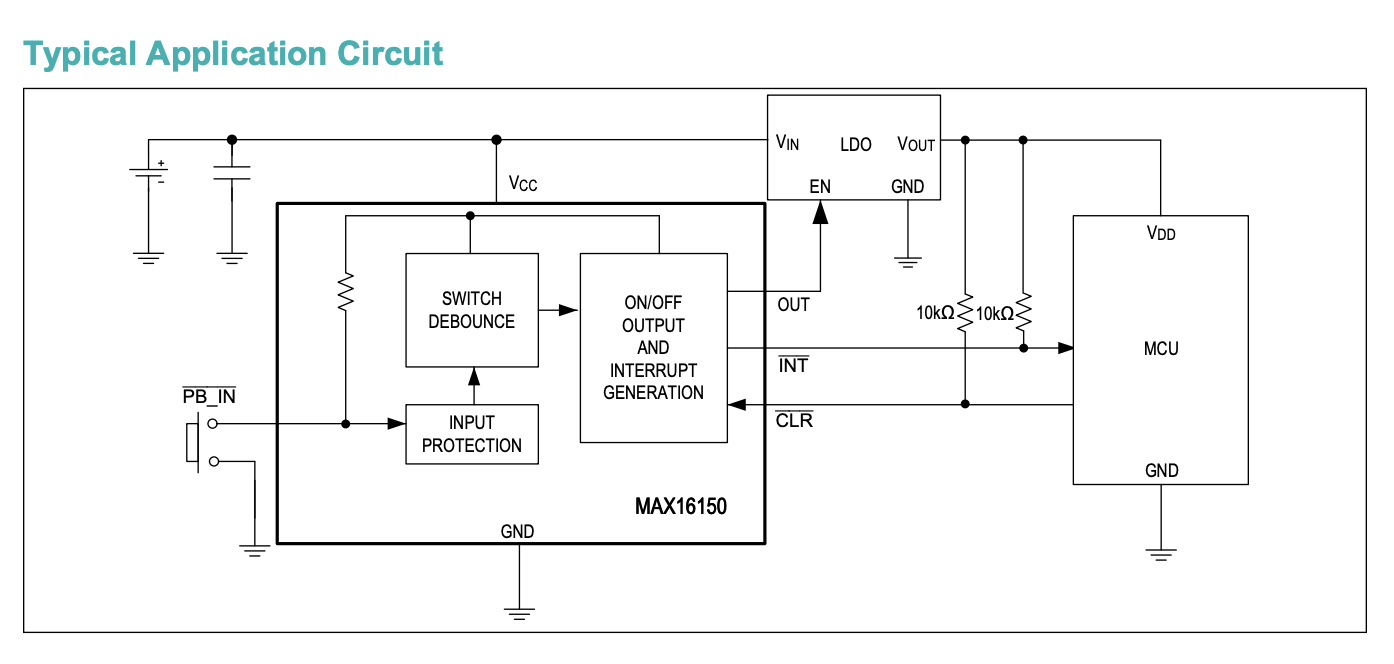
I saw a post on the Facebook group "Raspberry Pi and DIY Projects" where someone was using the MAX16150 IC to handle power on/off for their Pi, and it inspired me to try and get my MAX16150-based circuit working.
![]()
One of the typical application circuits from page 16 of the MAX16150 datasheet, showing it controlling the enable pin on a power supply for a power-hungry device. The MAX16150 monitors a push button on its PB_IN pin. A short press of the button will either turn on the OUT pin, or if it's already on, send a brief low pulse on the INT pin. The MCU (the CM4 in my case) can detect this pulse and handle it gracefully, by e.g. starting a soft shutdown.
If you press the power button for 8 seconds, the MAX16150 will deassert the OUT pin (pull it low), cutting power to the downstream device. This is consistent with the power button behavior of most computers, tablets, and phones.
If the CLR pin goes low, the MAX16150 will deassert the OUT pin. This is used to give the MCU a way to shut off its own power, and also provides some power watchdog functionality -- if the power goes low for some reason, like a short circuit or a dead battery, the MAX16150 will shut off the power.
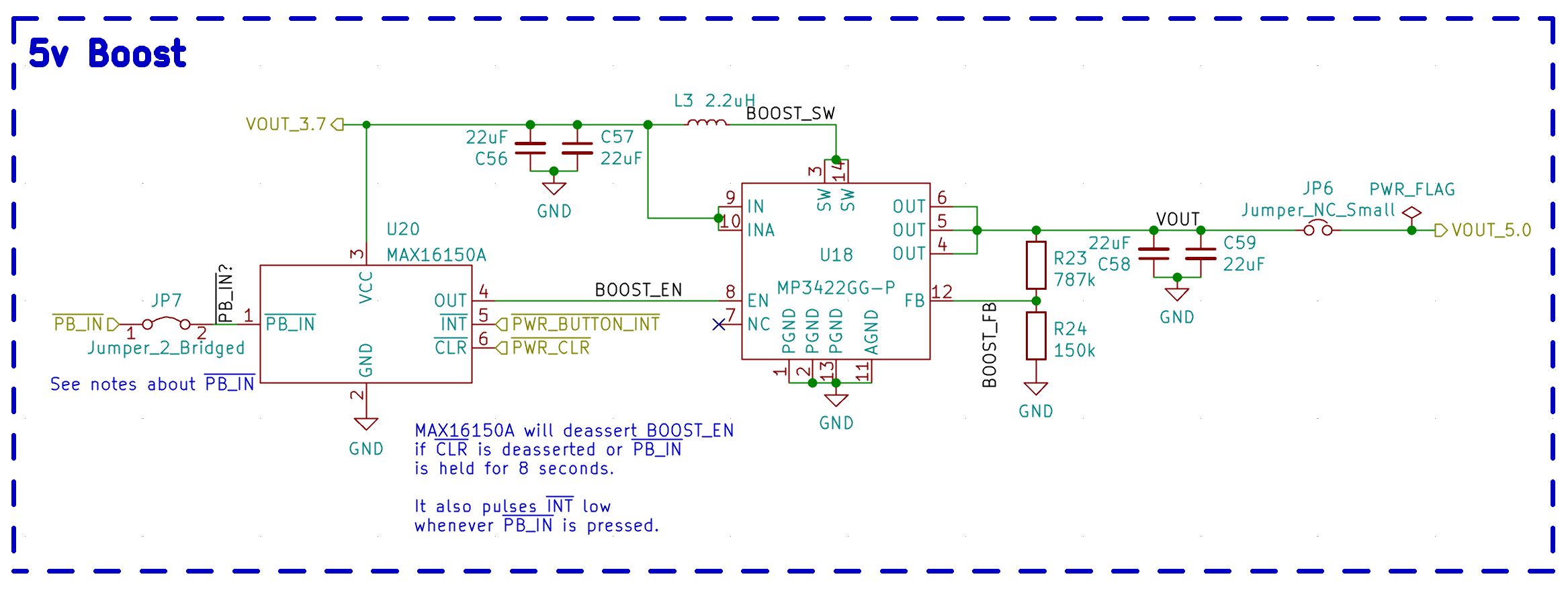
I more or less followed the typical application circuit above in my own design:
![]()
On my current revision of the PCB, the PWR_BUTTON_INT net connects to GPIO22 on the CM4, while PWR_CLR connects to the nEXTRST pin on the CM4.
nEXTRST is meant to indicate that power is good on the CM4, so it can be used for driving the RST pin on EXTernal devices that need to be powered when the Pi is powered. I assumed this would mean it would go low when the Linux kernel halts.
However, this approach has two problems:
- Turns out that nEXTRST is not pulled low when the kernel halts.
- nEXTRST stays low for around 200ms after 5V power is applied to the CM4.
The second problem is more severe. After asserting the OUT pin, the MAX16150 will ignore the CLR pin for 2x its interrupt period (32ms on my version. Different versions exist, but they're less "add to your Digikey cart" and more "call the factory to custom order".) When that 64ms has elapsed, if CLR is still low, the MAX16150 deasserts OUT again, which cuts power to the downstream device.
It turns out that this isn't an artificial delay on the nEXTRST pin - it actually just takes about 200ms for the CM4's 3.3V supply to start when 5V is applied.
I had originally worked around this by cutting the CLR<->nEXTRST trace on the PCB and then connecting CLR to 5V with a resistor. I then connected an extra push button between CLR and ground, to give me a way to cut power. However, this meant the Pi had no way to turn off its own power, and I had to manually click that second button any time I did a shutdown, or it would sit there, halted, drawing a nontrivial amount of power.
I've improved on this bodge in a way that I think is suitable to incorporate into my next PCB revision:
- I cut the PCB trace near the CM4 connector to disconnect it from the CM4's nEXTRST pin.
- I bridged it to a GPIO trace that I'm not currently using.
- I changed the 5V<->INT resistor for a 10k, and added a 20k resistor to ground.
This causes the INT pin to come up as soon as the 5V supply is good, but also keeps the voltage at a safe enough level for the GPIO pin, which is only 3.3V-tolerant.
At bootup, the GPIO pin seems to have a weak pull-down resistor, so the INT pin ends up with around 3.0V on it instead of 3.3V, but this is high enough for the MAX16150 to treat it as high.
With the following configuration in /boot/config.txt, I now have startup and shutdown behavior that works exactly as I intended.
dtoverlay=gpio-shutdown,gpio_pin=22,active_low=1,gpio_pull=up,debounce=10
dtoverlay=gpio-poweroff,gpiopin=17,active_low=1
I should have a few more updates for you shortly - I'm working on a new revision of the PCB which incorporates these fixes, as well as some other modifications I've had to make, and I'd like to double-check some other functionality before I commit to another PCB spin, in case I need to make more changes.
-
Attempting to tune the touchscreen controller
10/21/2022 at 11:15 • 1 commentFor reasons documented in a previous log entry, I am using the GT9110 touchscreen controller from Goodix. (Essentially, this is the only suitable touchscreen controller I could find in a footprint that I could actually use without spending hundreds of dollars per PCB revision.) In a later log entry, I got the GT9110 and Linux talking to each other.
Goodix is quite a frustrating company to buy from as a hobbyist. In comparison to some chip manufacturers like TI, who publish loads of documentation about their chips on the internet, Goodix is very stingy with their documentation. As far as I can tell, there's no way for hobbyists to get the documentation except hoping to find a leaked datasheet posted online somewhere. When you do find a datasheet, it's not particularly helpful. Some guidance on how to tune your touch panel (rather than just a table of registers with ~5 words about each) would be nice.
![]()
Goodix being extremely unhelpful to someone trying to design a board with their touchscreen controllers. Maybe I'll try reaching out to whatever AliExpress vendor I bought these chips from. I doubt they'll have the documentation, though.
Trying to tune the touchscreen controller
So I had the touchscreen detecting my touches, but it also detects phantom touches; mostly along a vertical line a quarter of the way in from the right side of the screen.
To recap how capacitive touchscreens work: The screens contain two layers of transparent traces, typically made of ITO, a transparent conductor. On one layer, you have traces going across the screen horizontally; in the other layer, traces go across the screen vertically. (This website has a pretty good graphic explaining this.) The touchscreen controller will send a signal to each "drive" trace (in my case, horizontal) and measure how much of this signal capacitively couples to each "receive" trace (vertical). When you bring your finger near the screen, some of the signal from the drive line will couple to your finger instead of the receive lines, which makes a measurable difference in coupling.
I have a few hypotheses as to what might be happening:
- That channel might have a bad connection on the board
- The chip itself might have a fault on that channel
- That channel might be receiving EMI from some nearby components, either on the PCB itself or in the touchscreen/LCD panel. Potentially this could be crosstalk between the transmit and this receive trace.)
I got a hold of a programming guide for the GT911 (the little sibling to the GT9110 -- same family, but fewer channels. I bet it's the exact same silicon die inside.) This gives me information on the i2c register maps.
(Aside: Apparently these chips support a mode called "HotKnot" in which two touchscreens can transfer data to each other!?!? What a bonkers feature.)
These are the registers which seem relevant to tuning sensitivity:
Address Name Notes 0x8053 Screen_Touch_Level This seems to be the signal level threshold above which a touch begins to be reported. Higher numbers = less sensitive. 0x8054 Screen_Leave_Level This seems to be the signal level threshold below which a touch stops being reported. Higher numbers = less sensitive. 0x806b Pannel_Tx_Gain The lowest 3 bits set the DAC gain, where 0 produces the largest signal and 7 producest the smallest signal. 0x806b Pannel_Rx_Gain The lowest 3 bits set the ADC gain. It seems like 7 is the most sensitive and 0 is the least sensitive. 0x806d Pannel_Dump_Shift Setting the lowest 3 bits to N > 0 will cause the touch signals to be shifted by N bits left. This would be useful if I wanted even more receive gain than Pannel_Rx_Gain can give, but I want less. I'd like to be able to overwhelm any noise by cranking the Tx power up and decreasing the RX sensitivity. Unfortunately, the configuration I had started with was already using 0 for the ADC and DAC gain, so it was already producing the strongest signal with the least Rx amplification.
Other registers
I have played with some other registers:
Address Name Notes 0x8062 Drv_GroupA_Num The 5 lowest bits on these two set the number of channels used on each transmitter group. There are 42 total transmit channels available, of which I'm using 40. By setting these so they total 40 instead of 42, my panel became a bit better-behaved and also got rid of a gap at one end of the screen. Drv_GroupA_Num has a flag "All_Driving", and Drv_GroupB_Num has a flag D_Freq; I'm not sure what either of these do. 0x8063 Drv_GroupB_Num 0x8067 Pannel_BitFreq_L These configure the fundamental frequency of the clock driving GroupA and GroupB. 0x8068 Pannel_BitFreq_H 0x8065 FreqA_factor These act as multiplication factors on the fundamental frequency. 0x8066 FreqB_factor When I tried out different driving frequencies, I either saw no improvement or a drastic deterioration of touchscreen function.
As for a faulty channel or bad connection on the board: I've already tried re-reflowing the flat flex connector, which had no effect. Perhaps I should take a look at the GT9110 chip itself under the microscope and make sure all the pins are well-soldered. (If there's a running theme with this project, it's that I keep discovering pins which aren't connected properly.)
-
Trying my hand at driver development
10/18/2022 at 07:19 • 1 commentOne issue which contributes to the backlight flicker is the undervoltage protection (UVLO) feature of the TPS61177A. This is configurable over i2c, but defaults to 3.5V, which is pretty high.
In order to set this at startup, I decided to try and write a kernel driver for the TPS61177A. I partly followed https://docs.kernel.org/i2c/writing-clients.html and partly cargo-culted some stuff (mostly related to regmap) from the sn65dsi83 driver. (I've poked around in that driver in previous debugging sessions, which helps me understand its structure more than some other random i2c device driver.)
The driver essentially just sets the 0xa2 register to the value 0x02, which corresponds to a UVLO voltage of 3.0V. (Ideally, they'd have options between 3.0 and 2.55, but alas...)
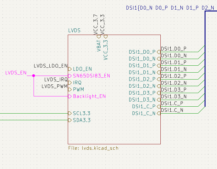
After a few hours of struggle, I got this to configure the UVLO voltage over i2c, but I've run into a hardware-level problem with this approach: in order to save GPIO pins, I used the same GPIO for both the sn65dsi83's enable pin and the tps61177a:
![]()
Screenshot of part of my schematic, showing that the enable pins for the LVDS bridge (sn65dsi83) and backlight driver (tps61177a) are shorted together. This means that the drivers for both chips are competing for control over the GPIO pin; this seems to cause the second driver to fail to load. (In this case, the sn65.)
There's an easy workaround, for now: I can manually tell the tps61177a to save its configuration to EEPROM. Long-term, I'd like to reduce the number of manual steps that someone would have to take in order to get this board working, and that means either a driver like the one I've written, or some userspace solution like a startup script.
-
Backlight flickering investigation + device tree overlay for the battery charger.
10/16/2022 at 07:37 • 0 commentsI've been investigating the backlight flickering that I showed in my previous log entry. My main hypothesis was that the long wires between my breakout board and my main PCB were adding too much inductance, causing increased ripple. I had moved an input decoupling capacitor to the breakout board, which helped some but didn't entirely solve the problem. Adding more capacitance on the input side didn't help much more.
One thing I noticed is that the problem drops entirely when the tablet is connected to the charger. This made me suspect that maybe my battery is the problem.
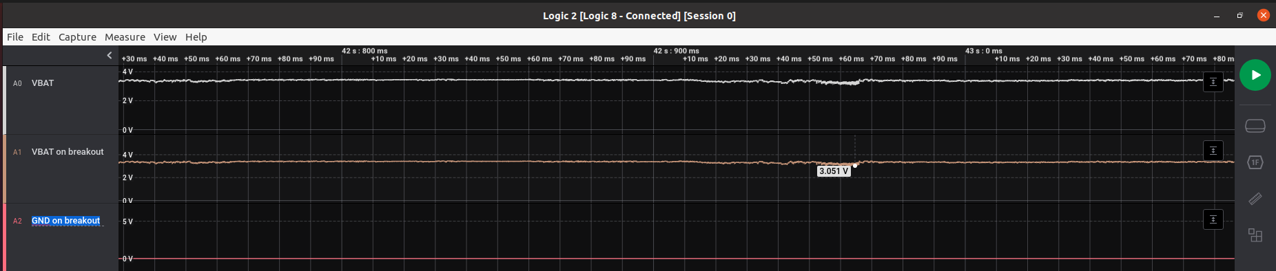
![]()
Looks like there isn't much difference between the VBAT measured at the battery terminals and VBAT measured on the breakout board (at least at speeds the Saleae can measure; it's possible that the breakout board sees switching transients.)
But yikes, the battery is dipping ~400mV under load? That seems like a lot. Assuming that's happening while the board is drawing 2 to 4 amps, that's 100 to 200 milliohms of internal resistance on the battery. I dunno what the internal resistance of a LiPo battery is supposed to be, but this feels high. Perhaps my test battery is aged - internal resistance goes up with use + abuse. (I'm using a separate battery for testing; just a random 2000mAh cell I had lying around, because the iPad battery is glued to the back of the case and doesn't have wire leads, just spring terminals.)
On the topic of battery health...
I've heard one way to keep lithium ion/polymer batteries healthy is to limit the maximum charge voltage to something lower than 4.2V, like 4.0-4.1V. The battery charge IC I'm using (TI's bq25895) supports this functionality, so I've added a device tree overlay which sets this parameter. This also lets us read the battery voltage and charging current (but not discharge current?) easily in Linux:
meatmanek@cm4:/sys/class/power_supply/bq25890-charger$ cat status
Charging
meatmanek@cm4:/sys/class/power_supply/bq25890-charger$ cat voltage_now
3924000
meatmanek@cm4:/sys/class/power_supply/bq25890-charger$ cat current_now
-400000
meatmanek@cm4:/sys/class/power_supply/bq25890-charger$ cat constant_charge_voltage_max
4096000
Hopefully this helps keep the 12-year-old iPad battery in good working condition.
-
Starting to look like a tablet
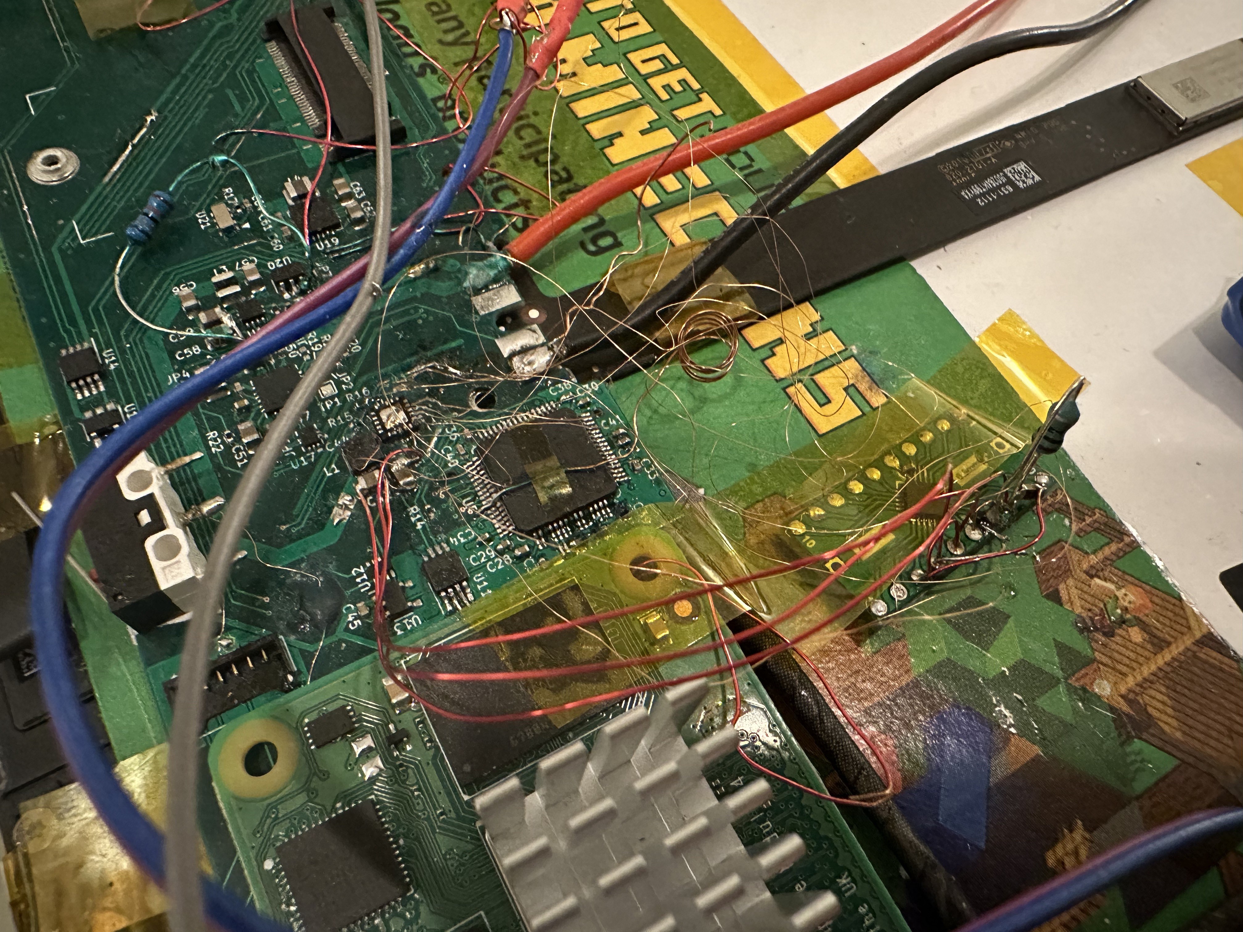
10/15/2022 at 07:10 • 0 commentsI soldered my backlight controller IC onto a QFN breakout board and bodged some connections over to my PCB, so that I could view my LCD without having to provide an external backlight.
![]()
The mess of wires here is mostly bodge connections from that QFN breakout to traces on the PCB -- battery power, i2c, PWM and enable pins, and the anode + cathode pins for the LCD backlight. This works, but has some issues: the backlight flickers a lot when the Pi is under load (or using wifi or something?) I think the backlight controller is hitting its under-voltage lockout. At first, I had left the large decoupling cap on the main PCB, but in this configuration the backlight would strobe for about a second on boot, then would shut off. Moving the capacitor to the breakout board helped, but the flicker remains. I may add more capacitance.
I also think one of the LED strings isn't connected correctly, causing the "stagelight" appearance at the top of the screen.
(The backlight in the iPad, like many other LCDs, is 6 strings of LEDs:
![]()
Example schematic from the datasheet for the TPS61177A, the backlight controller I'm using. This keeps the voltage at something reasonable -- about 20V in the iPad -- and also means that a single LED failure doesn't cause the whole backlight to go out.)
The video
The touchscreen doesn't work quite right - it's detecting phantom touches. I've decreased the sensitivity, which helps slightly, but also makes it miss some real touches. This makes it pretty frustrating to use. (In the video, you can see me struggle to shut down the Pi using the shutdown menu while the touchscreen keeps trying to read MagPi.) The GT9110 chip I'm using has terrible publicly-available documentation, so tuning its configuration will be lots of trial and error.
Even with all these problems, it's really beginning to feel like a tablet.
Put a Raspberry Pi CM4 into an original iPad
Open up a 2010 iPad, remove its logic board, and fabricate a new board based around the Raspberry Pi CM4.