Evan
Evan-
Power supply testing, part 2
07/08/2021 at 06:05 • 1 commentI assembled the front of my board yesterday (dealing with 0402 components is tedious. I really should just pay JLCPCB to solder on most of the passives for me.) Today, I wanted to quickly test the power supply to make sure I hadn't broken anything yesterday.
I attached a battery (I managed to find another LiPo battery buried in a drawer), checked output voltage (5.1V ☑️), wired up the raspberry pi (which booted.) Everything seems to work as well as it did two days ago. However, I tested a few things that I hadn't tested before, and discovered a few unfortunate things:
When I plugged in the USB charge cable, the red LED on the Raspberry Pi shut off. However, the Pi didn't actually shut down - I think the input voltage dropped just enough that the Pi turned off the LED. (The USB charger I'm testing with only puts out about 4.5V.)
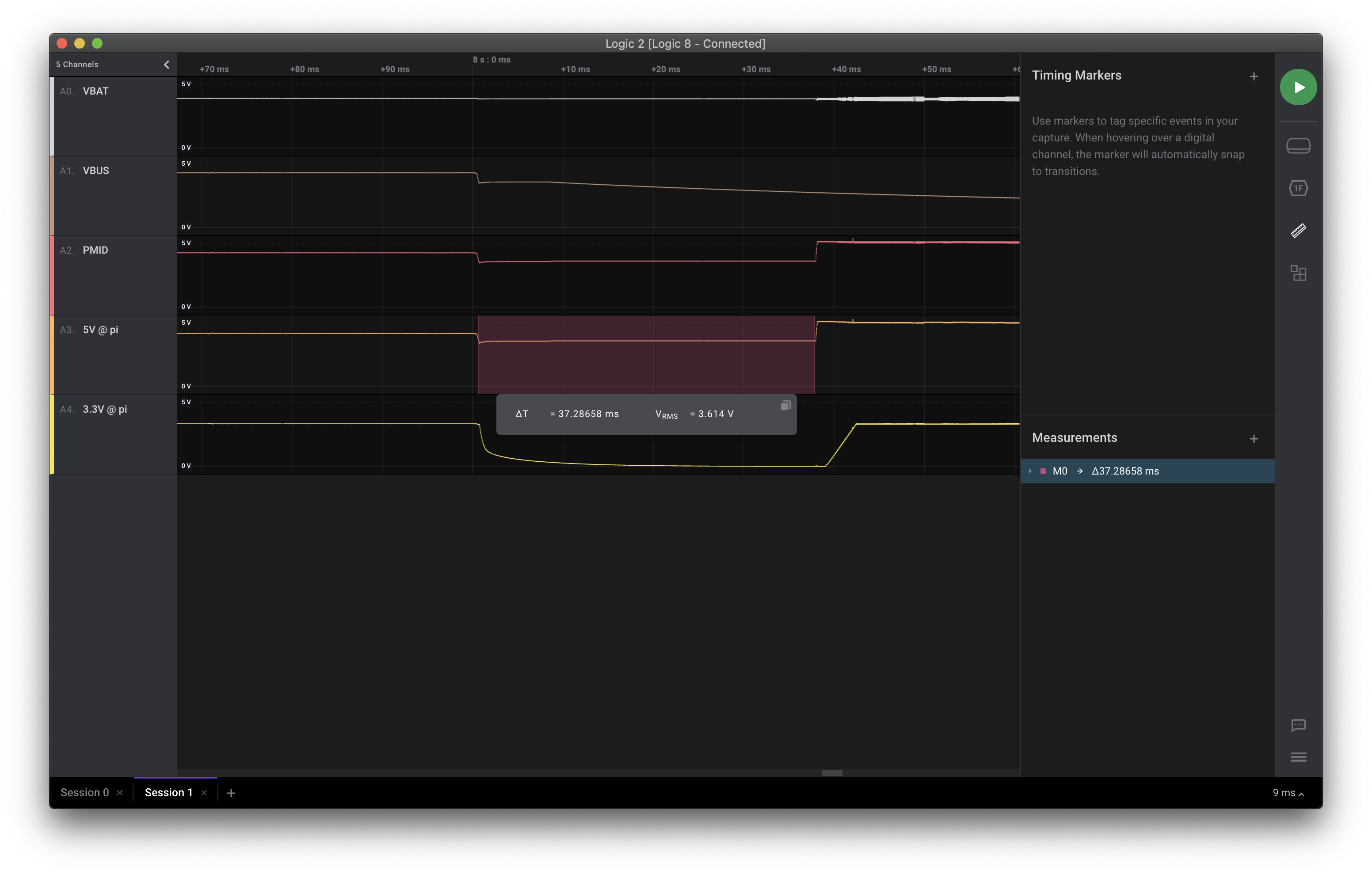
However, when I unplugged the USB cable, the Pi did actually shut off. Turns out, it takes about 38ms for the bq25895 to start the boost converter after VBUS drops to 0, so my 5V output drops to about 0.2V below Vbat, so about 3.6V in this case. (probably being fed entirely through the external Schottky diode.)
![]()
Screenshot of Logic 2 showing the voltage drop on the 5V output when you unplug the USB input cable. From this trace of the various voltage rails, we can see that PMID (the 5v output of the bq25895) and 5V @ pi (the pi's 5v rail, connected by wire to PMID - I just wanted to make sure there wasn't too much voltage drop on the wire) drop down to about 3.6V. This is low enough that the Pi shuts down its 3.3V rail.
Because of this issue and the risk of USB voltage being passed directly to the Pi if the bq25895 negotiates a higher voltage, I think I'm going to have to add a separate boost converter like the SuperPower-RPi project does. (I based my bq25895 schematic heavily off of theirs.)
Thanks a ton to Seth K from the SuperPower discord for his input on this.
-
Power supply testing
07/06/2021 at 06:31 • 0 commentsSo I finally finished designing v0.0.1 of my PCB, and had them made by JLCPCB. This prototype has:
- touchscreen controller
- MIPI-DSI to LVDS converter
- LED backlight driver
- battery controller/boost converter
- audio codec, speaker amplifiers, and footprints for speaker and headphone connectors
- connectors for the 30-pin dock board and the ambient light sensor
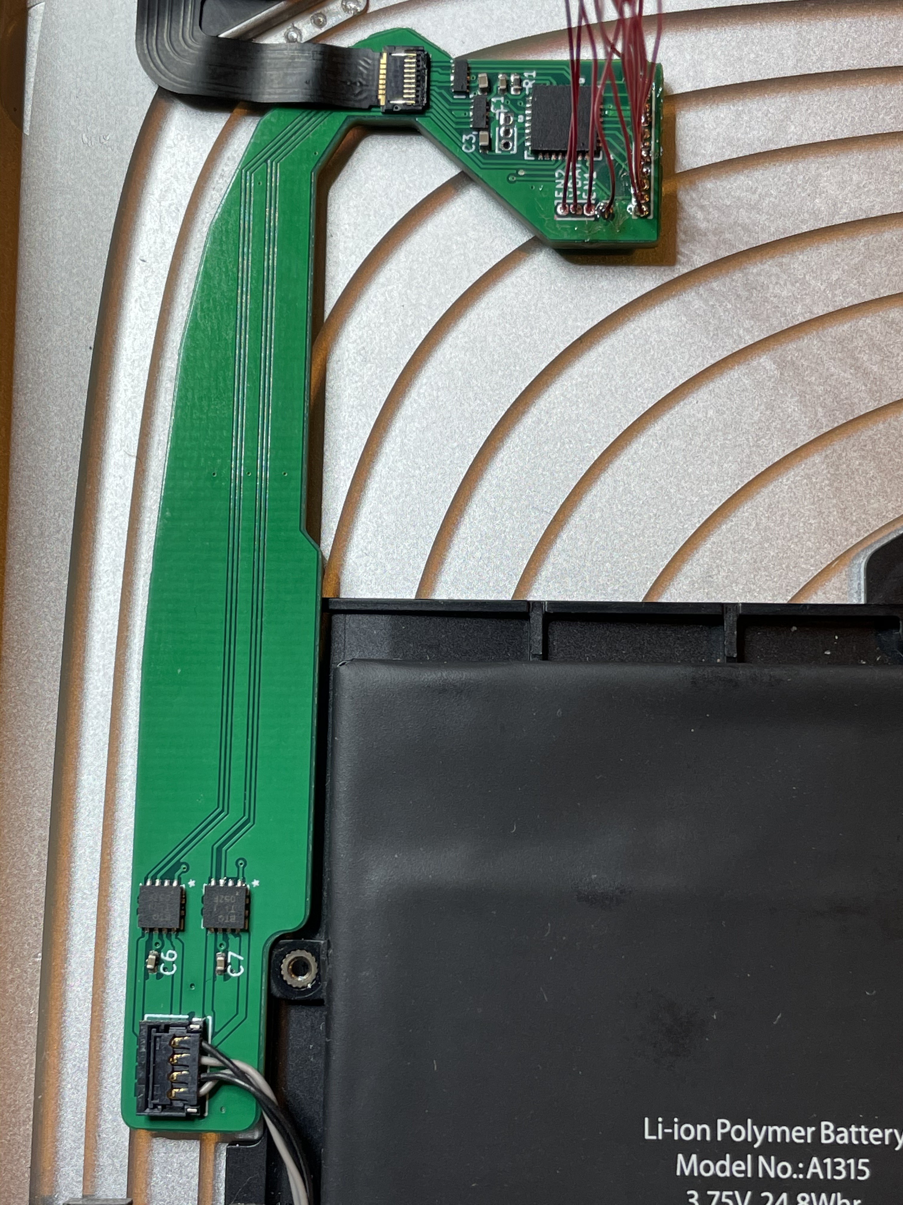
![]()
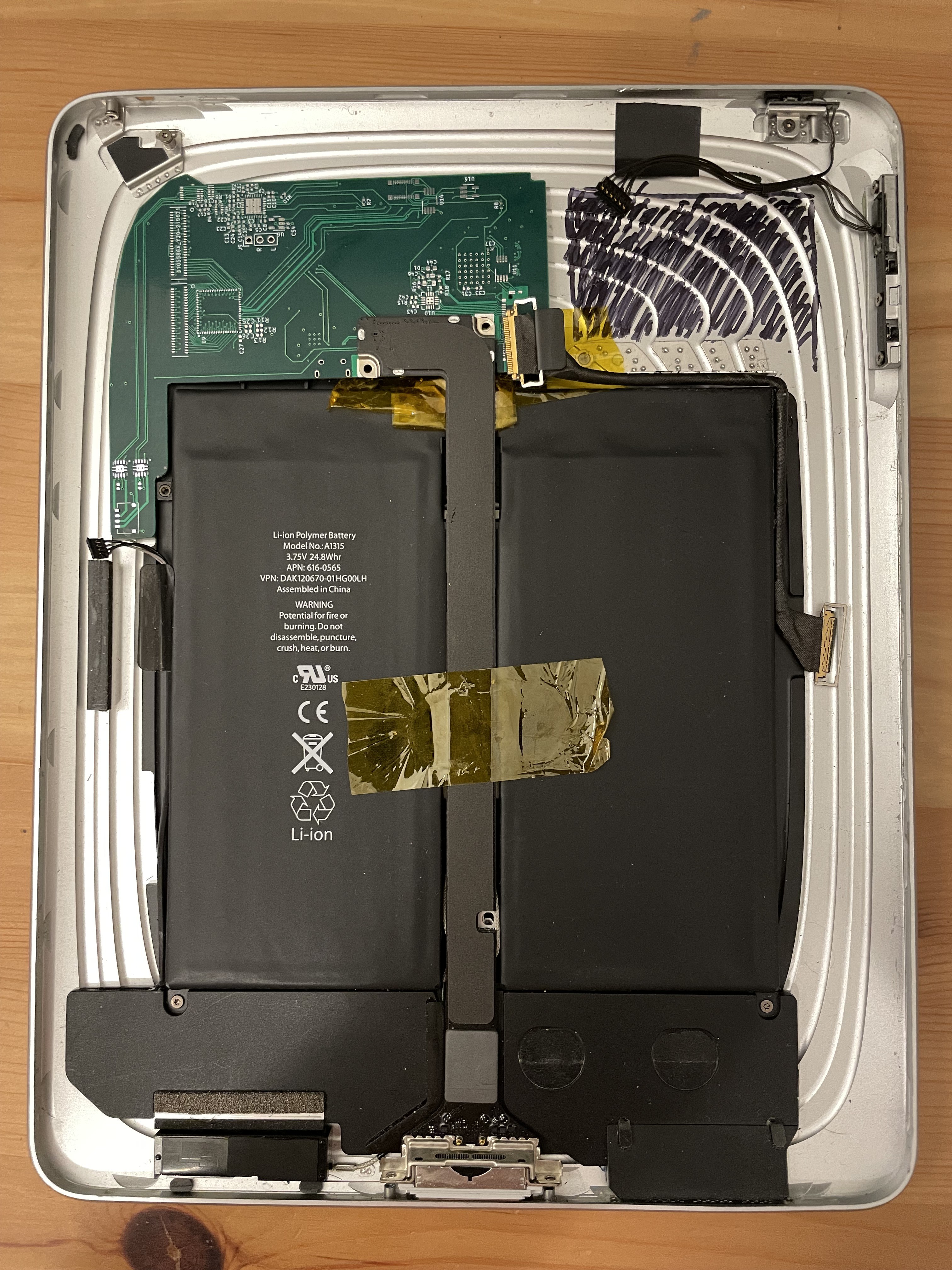
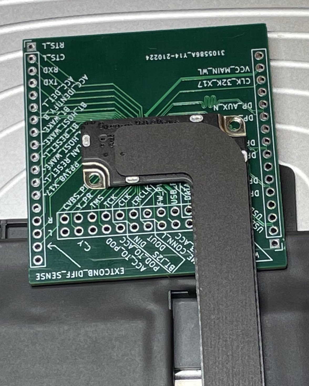
testing the fit of my v0.0.1 prototype board inside the iPad. Instead of having the two 100-pin connectors for the CM4 like the final board will have, this version of the PCB is designed sort of like a Pi HAT, with a 40-pin header on the bottom. It also receives the video signal through a 15-pin ribbon cable, and has an extra USB micro B connector wired to the battery controller. This design allows for safer testing: I can connect only the pins that are needed to test one feature at a time.
I've assembled only the bottom of the board so far (the battery controller and the DSI-to-LVDS converter), and have been working on testing the battery controller.
My battery controller is adapted from Pi-Charger.sch from the SuperPower-RPi project, which is essentially the example schematic for the bq25895 battery controller from TI. In the SuperPower board, they use a separate boost converter to go from battery voltage up to 5V, but on my board I decided to use the bq25895's built-in boost converter, which can provide 3.1A at 5V if you add an extra diode. This approach has risks, and I will revisit this decision.
First thing I did to test it was give it 3.6V on the battery+ and ground connectors, hoping to see 5 volts output, but no dice. After scanning through the i2c registers, I eventually noticed that it was complaining about the thermistor being missing. After adding a 10k resistor... still no dice. Turns out I needed to pull the OTG pin high. Good thing I broke that out to a test pad!
I futzed around for a while with various approximations of the iPad's battery (3x NiMH AA's in series; some old, fairly degraded 18650s out of a battery pack from a broken bike light). These all had too much internal resistance to supply the ~15 watt spikes required to boot the RPi 4, and would trigger the bq25895's undervoltage shutoff. Eventually, I gained enough confidence in the board to test with the iPad's actual battery. This worked great!
![]()
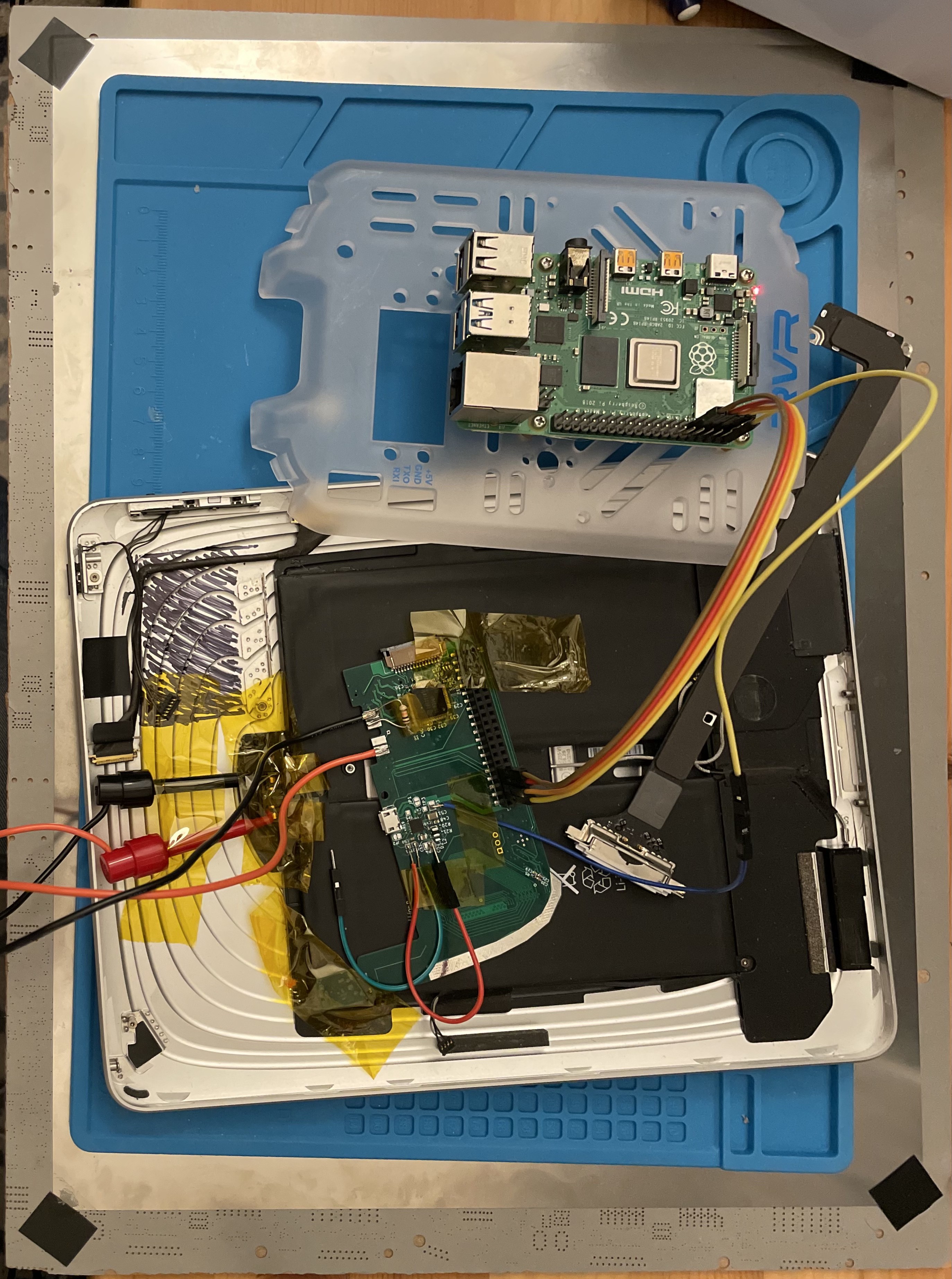
Prototype board connected to the iPad's battery, powering a Raspberry Pi 4 It seems like the iPad battery is in pretty good condition - at least, it's been holding a charge, and still has very low internal resistance. I measured maybe 50mV of voltage droop when booting the Pi 4.
Up next is probably testing the LED backlight driver, then after that I can test the LVDS controller. I may or may not be able to test the touchscreen controller: the FFC connectors are backwards. 🤦♂️
-
Attempting to write a device tree overlay for the soundcard
03/22/2021 at 03:54 • 1 commentSince my last log, I connected the other ends of the magnet wires to female header pins so that I can attach to my RPi 4. I really, really would recommend against trying to do it this way. I'm either gonna spend the board space and use 0.1" headers next time, or go for something easy to solder like an FFC so I can make a matching breakout board.
In the mean time, I've tested the board a bit, and have been working on making it work under Linux.
For basic testing, I used command line tools for I2C (i2cdetect, i2cset, i2cget from the i2c-tools package. From this, I was able to confirm that the codec powers up successfully, I can speak to it over i2c, and that jack detection works. (This codec can tell the difference between a TRS stereo headset and a TRRS stereo/mic headset, based on the resistance between the different pins.)
I still have no idea whether I can actually make sounds with this thing, though. To get sound, I need to:
- Toggle GPIO pins to enable the dual LDO and the codec
- Configure the codec via i2c so that it knows which of its several output pins to use, and what format we'll be sending on its PCM/I2S pins.
- Actually send I2S to it.
I could probably script all that, using python or bash or something, but since in the end I want to make this work as a fully-supported alsa/pulseaudio/whatever output, I started learning how to do this Properly™. The basic approach is to make sure the kernel has a module available for the codec, then write a "device tree overlay" describing the board.
The Linux kernel source already have a driver for the TLV320AIC3104, but they aren't included by default in Raspberry Pi OS. After cloning, configuring to enable the tlv320aic3x driver, and rebuilding the kernel, I have the snd_soc_tlv320aic3x module available.
Next, I need a device tree overlay for my board. This will tell the kernel what hardware I've attached to the computer, and if all goes well, the kernel should load and instantiate the appropriate drivers.
The Raspberry Pi website has a decent page about device trees, overlays, and parameters. The kernel documentation also has some useful pages about it: Linux and the Device Tree. It's also helpful to I cargo-culted my first version of my overlay, compiled it, put it in /boot/overlays, added it to config.txt, and rebooted, and... how do I know if it worked? After playing around and searching for things, I was able to find a couple useful debugging tips:
- Check dmesg for anything obvious.
- On Raspberry Pi devices only, you can get bootloader logs with
sudo vcdbg log msg
- This forum post recommends booting without the overlay enabled, then load the overlay at runtime with the dtoverlay command while running udevadm monitor. I've found it's also helpful to be running `dmesg -w` also.
# in one terminal:
dmesg -w
# in a second terminal:
sudo udevadm monitor
# in a third terminal:
sudo dtoverlay pipad
You'll find devicetree-related messages in dmesg often have the prefix "OF:", which I think refers to OpenFirmware, where the device tree concept was originally created.
Unfortunately, this doesn't shorten the iteration cycle -- every time your overlay fails to properly apply, you need to reboot to get back to a clean state. (It looks like you should be able to remove an overlay with dtoverlay -r, but this doesn't work if your overlay doesn't apply cleanly.)
After iterations, I've settled on this .dts file:
/dts-v1/;
/plugin/;

/ {
    compatible = "brcm,bcm2835";
    fragment@0 {
        target = <&gpio>;
        __overlay__ {
            aic3104_reset: aic3104_reset {
                brcm,pins = <17 27>;
                brcm,function = <1 1>;
                brcm,pull = <1 1>;
            };
        };
    };

    fragment@1 {
        target-path = "/";
        __overlay__ {

            vcc30: fixedregulator@1 {
                compatible = "regulator-fixed";
                regulator-name = "fixed-supply";
                regulator-min-microvolt = <3000000>;
                regulator-max-microvolt = <3000000>;
                gpio = <&gpio 22 1>;
                startup-delay-us = <70000>;
                enable-active-high;
                vin-supply = <&vdd_3v3_reg>;
            };
            vcc18: fixedregulator@2 {
                compatible = "regulator-fixed";
                regulator-name = "fixed-supply";
                regulator-min-microvolt = <1800000>;
                regulator-max-microvolt = <1800000>;
                gpio = <&gpio 22 1>;
                startup-delay-us = <70000>;
                enable-active-high;
                vin-supply = <&vdd_3v3_reg>;
            };

            amp: analog-amplifier {
                compatible = "simple-audio-amplifier";
                enable-gpios = <&gpio 17 1>;
                VCC-supply = <&vdd_3v3_reg>;
            };
        };
    };

    fragment@2 {
        target = <&i2c1>;
        __overlay__ {
            tlv320aic3104: tlv320aic3104@18 {
                #sound-dai-cells = <0>;
                compatible = "ti,tlv320aic3104";
                reg = <0x18>;

                reset-gpios = <&gpio 27 0>;

                AVDD-supply = <&vcc30>;
                DRVDD-supply = <&vcc30>;
                DVDD-supply = <&vcc18>;
                IOVDD-supply = <&vdd_3v3_reg>;
            };
        };
    };

    fragment@3 {
        target = <&i2s>;
        __overlay__ {
            status = "okay";
        };
    };

    fragment@4 {
        target = <&sound>;
        __overlay__ {
            compatible = "simple-audio-card";
            i2s_controller = <&i2s>;
            status = "okay";
            simple-audio-card,name = "pipad";
            simple-audio-card,format = "i2s";

            simple-audio-card,bitclock-master = <&dailink0_master>;
            simple-audio-card,frame-master = <&dailink0_master>;

            simple-audio-card,widgets =
                "Microphone", "Microphone Jack",
                "Microphone", "Internal Microphone",
                "Headphone", "Headphone Jack",
                "Line", "Line Out",
                "Speaker", "Internal Speaker";
            simple-audio-card,routing =
                "Line Out", "HPLCOM",
                "Line Out", "HPRCOM",
                "Headphone Jack", "HPLOUT",
                "Headphone Jack", "HPROUT",
                "Microphone Jack", "MIC2L",
                "Internal Microphone", "MIC1L",
                "Internal Speaker", "LLOUT",
                "Internal Speaker", "RLOUT";
            simple-audio-card,aux-devs = <&>;
            dailink0_master: simple-audio-card,cpu {
                sound-dai = <&i2s>;
            };
            simple-audio-card,codec {
                sound-dai = <&tlv320aic3104>;
                system-clock-frequency = <12288000>;
            };
        };
    };
};
This loads cleanly, and causes the snd_soc_tlv320aic3x, snd_soc_simple_card, and snd_soc_bcm2835_i2s modules to be loaded. This looks like it ought to work, but at the moment:
pi@raspberrypi:~ $ aplay -l
aplay: device_list:272: no soundcards found...
pi@raspberrypi:~ $ ls /dev/snd
seq  timer
If things were working correctly, this ought to look something like:
pi@raspberrypi:~ $ aplay -l
**** List of PLAYBACK Hardware Devices ****
card 0: b1 [bcm2835 HDMI 1], device 0: bcm2835 HDMI 1 [bcm2835 HDMI 1]
  Subdevices: 4/4
  Subdevice #0: subdevice #0
  Subdevice #1: subdevice #1
  Subdevice #2: subdevice #2
  Subdevice #3: subdevice #3
card 1: Headphones [bcm2835 Headphones], device 0: bcm2835 Headphones [bcm2835 Headphones]
  Subdevices: 4/4
  Subdevice #0: subdevice #0
  Subdevice #1: subdevice #1
  Subdevice #2: subdevice #2
  Subdevice #3: subdevice #3
pi@raspberrypi:~ $ ls /dev/snd/
by-path  controlC0  controlC1  pcmC0D0p  pcmC1D0p  seq  timer
(This is what you see if you set dtparam=audio=on in /boot/config.txt). I'm stuck until I figure out why controlC0 / pcmC0D0p are missing.
-
Finally, things to solder!
03/09/2021 at 08:01 • 0 commentsMy most recent JLCPCB order arrived today, which contained:
- The i2s soundcard based around the TLV320AIC3104 from TI.
- Breakout board for the AXK770147G used to connect the logic board to the portrait dock connector daughterboard.
- Breakout board for the AA03-S024VA1 used to connect the logic board to the ambient light sensor.
I also included a stencil for the soundcard.
I soldered the breakout board for the AXK770147G with the drag soldering technique, which I definitely need to practice. I needed to do a lot of cleanup with solder wick, plus I seem to have destroyed some of the solder mask. After some basic continuity checking, everything seems okay (though now that I'm looking again, it seems like I may have a bridge between two pins on the bottom right.
![]()
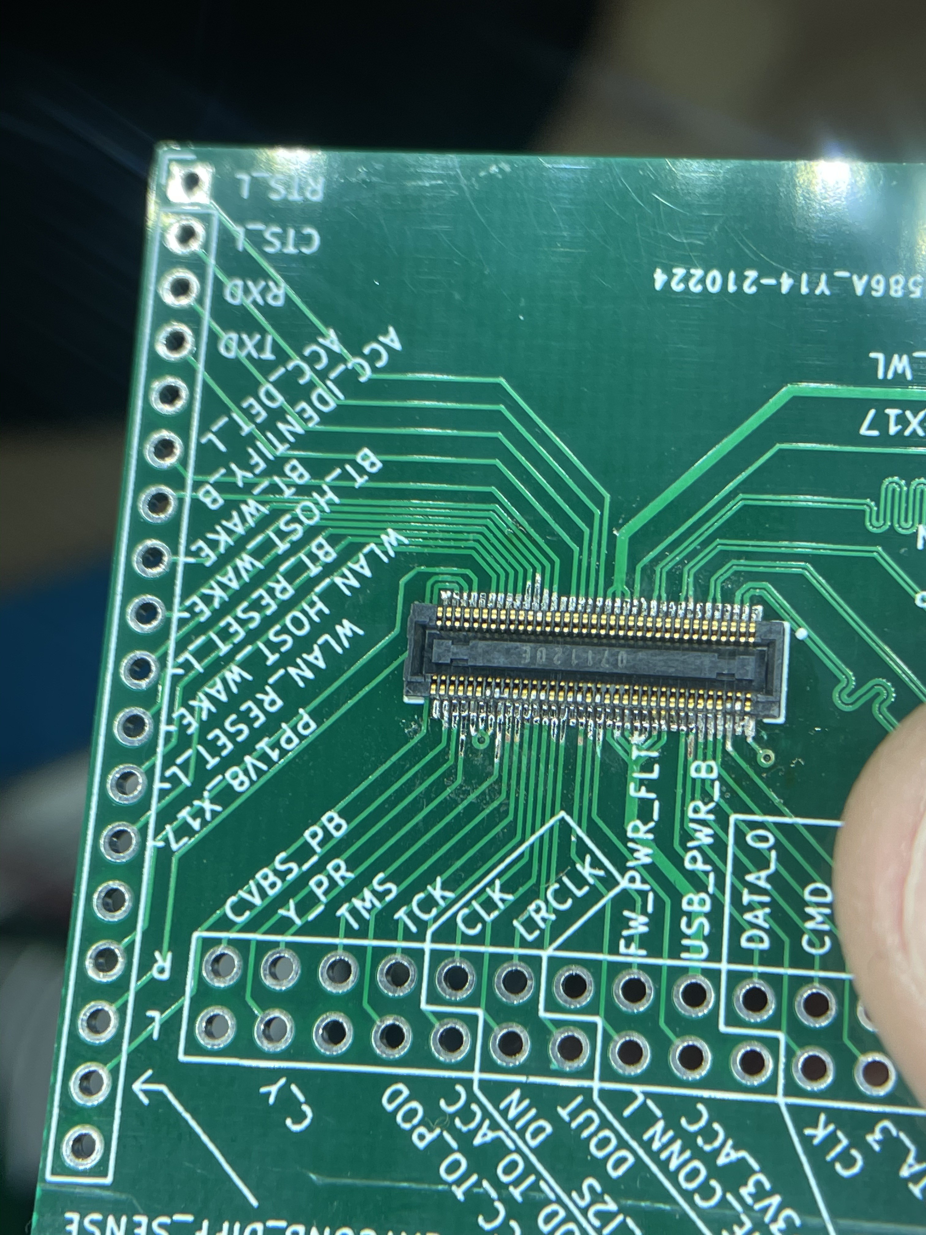
Unfortunately, it seems like I designed it upside-down. (It still pretty much works as a breakout, but I had intended for the double row of header pins to be on the top, not the bottom. Double check the orientation of critical connectors before routing! This isn't a big deal for this board (I mostly ordered this as a way to test continuity to pins on the 30-pin dock connector, and this board still works for that purpose, even if several of the pins are only accessible from the back.)
![]()
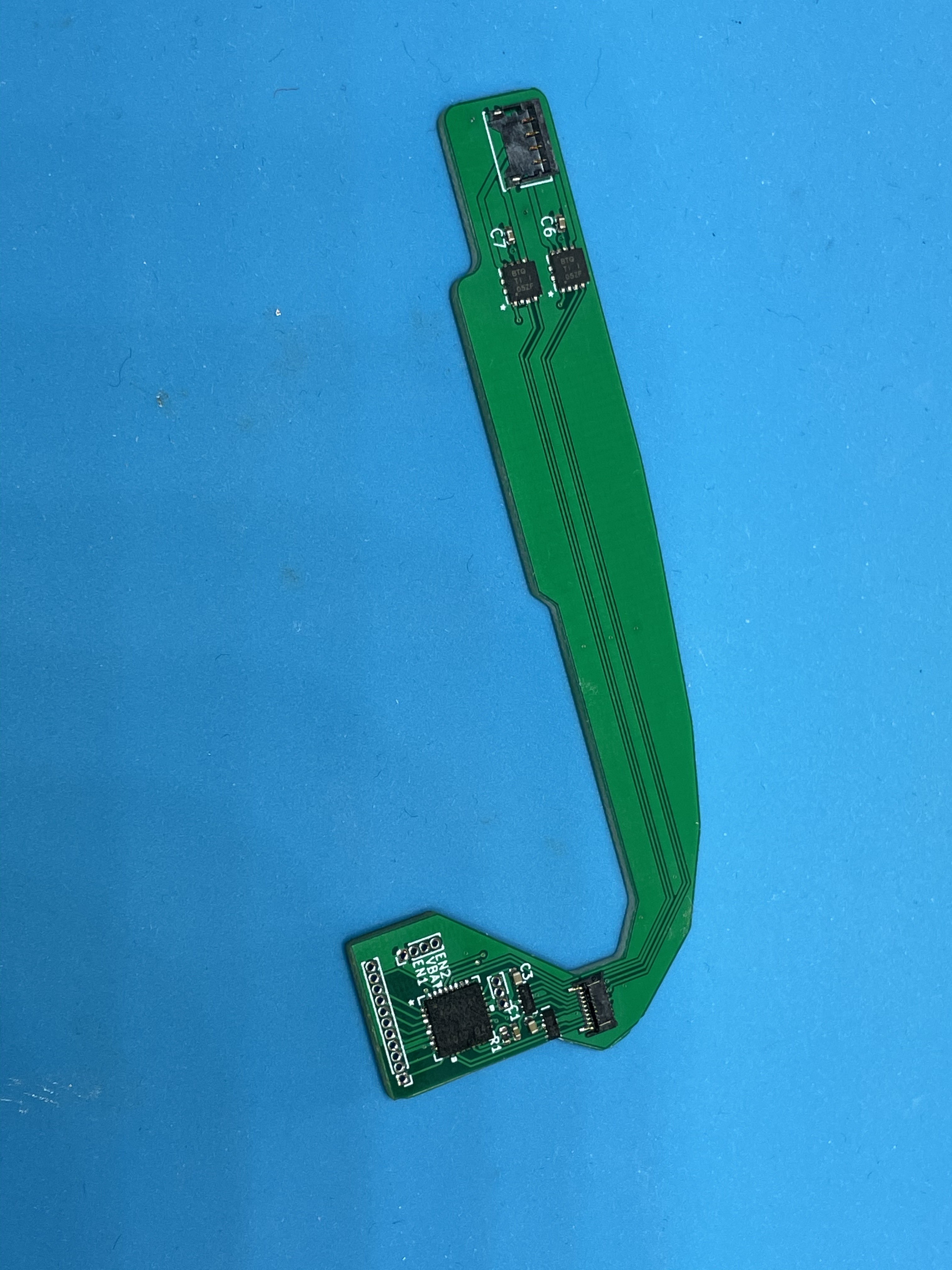
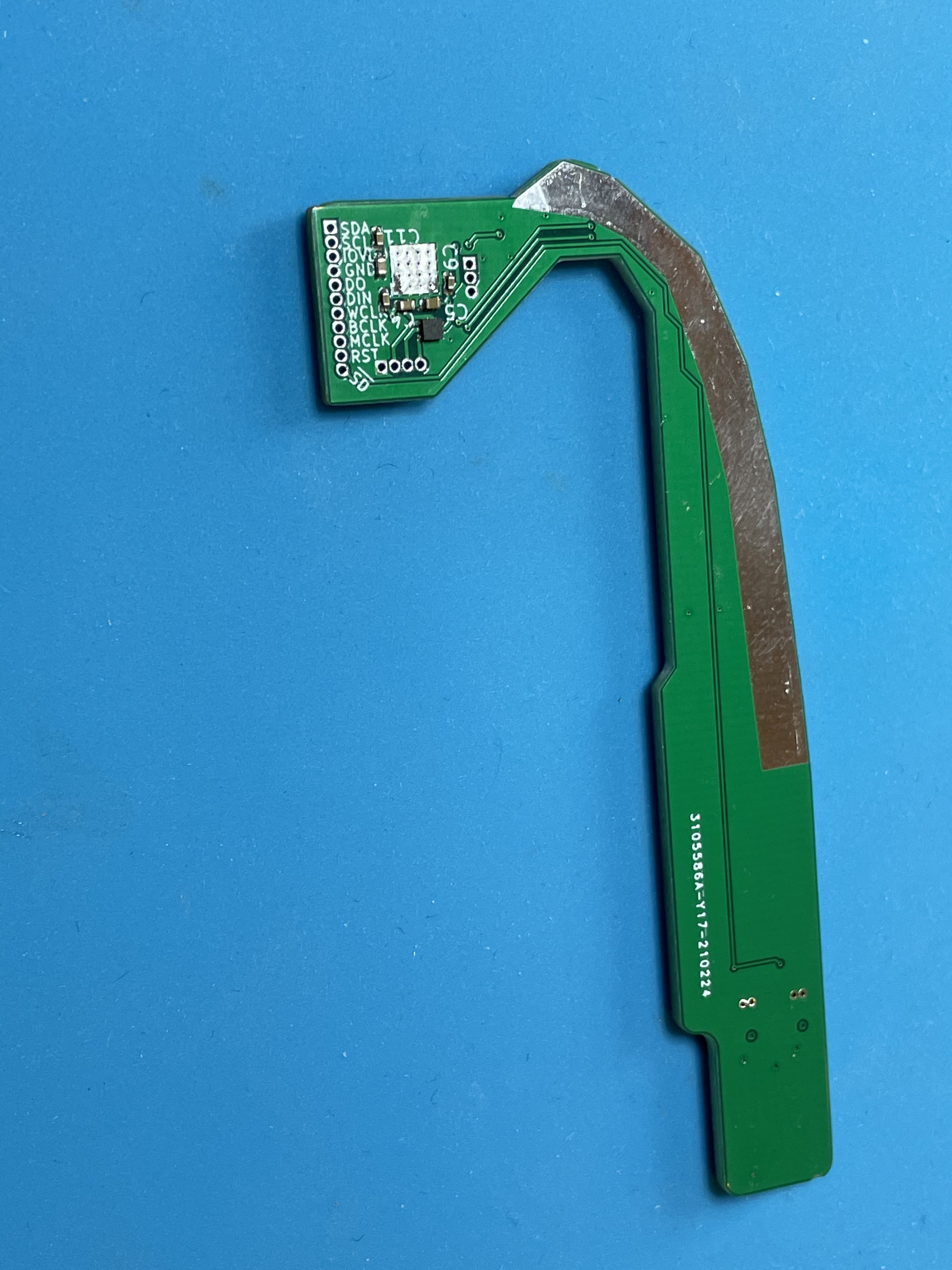
I also soldered the I2S board. (It's an odd shape because it's supposed to wrap around the touchscreen controller board.)
![]()
![]()
This went pretty smoothly, all things considered! This was my first time working with solder paste, stencils, and hot air. With the stencil ensuring that I had a reasonable amount of paste on each pad, I found the paste very forgiving. Squeegee some paste through the stencil, use tweezers to carefully place each part (nudging as necessary), and then gradually heat with the hot air station. Repeat for the back.
I caught a mistake with this I2S board pretty soon after I submitted the JLCPCB order -- I had laid it out with 0402 footprints for the 220uF capacitors, which you cannot get in such a small footprint. I've updated my board layout for 1206 footprints. I may end up adjusting the board so I can have JLCPCB assemble most of it for me -- put all the passives on one side, so I'm only doing the larger ICs. Before I reorder this board, I want to test it. In the mean time, I ordered the highest-capacity 0402 caps you can get on Digikey (22uF). This will mean I have terrible bass response, but I should still be able to test basic functionality.
(I'm tempted to redo this board with a codec with ground-centered "capless" headphone outputs. These ICs provide their own negative voltage rail with a charge pump, and can drive the headphone output to negative voltages. This avoids the need for bypass capacitors, and provides even better bass.)
![]()
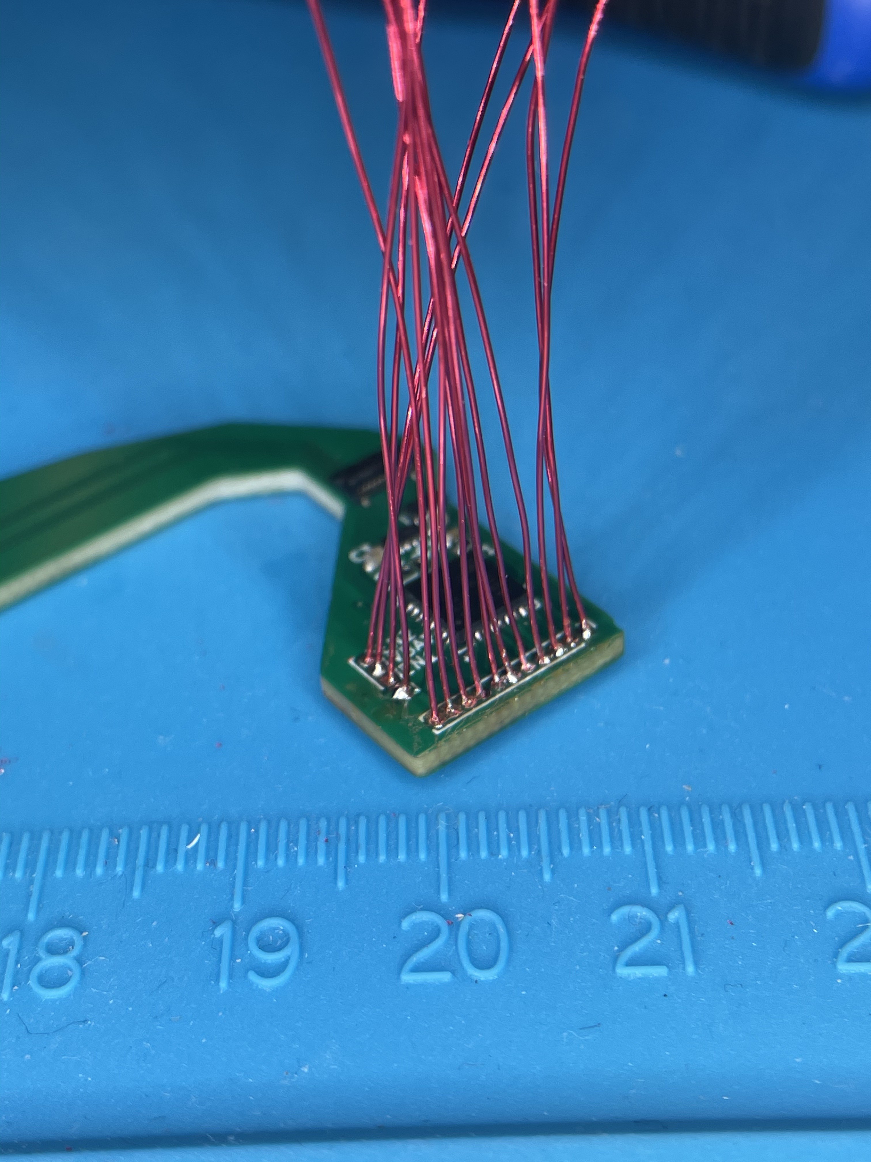
For some reason, I had decided to use 1mm-pitch header holes on this board. I guess I was hoping if I got the board right, I could leave it as is and use small wires to connect to other boards.
Most forms of hookup wire I have on hand have insulation that is larger than 1mm diameter, so I ended up going with enameled magnet wire. Magnet wire takes forever to strip.
I think in the future, for small-pitch headers, I might go for 1.27mm. The standard rainbow "Dupont" jumper wires that you can find for cheap with 0.1" male or female pins on either end seem to be 1.27mm-pitch ribbon cable, so it would be much easier to solder some ribbon cables in place. Either way, if I do header pins this small again, I'll buy actual header pins and get a breakout board to 2.54mm headers manufactured. Maybe I should just buy some generic FFCs and breakout boards?
![]()
Looks like the connectors are in the right place / orientation, at least!
Still to do on the soundcard:
- Solder the other end of those magnet wires to some female header pins that can mate with the RPi 4 / CM4IO's 40-pin connector + something that can provide power.
- Test out the board.
-
Video output research
03/02/2021 at 07:14 • 0 commentsWhile I wait for my audio board and breakout boards to show up, I started working on the video output side of things.
The Raspberry Pi CM4 has four ways to output video:
- 2x HDMI
- 2x MIPI DSI
- 1x DPI
- 1x Composite
I need to convert these into three different formats (in order of priority):
- LVDS (FPD-Link or OLDI maybe) for the LP097X02-SLA1 built-in display.
- DisplayPort for powering 30-pin video dongles such as the Digital AV Adapter (HDMI) or the 30-pin to VGA Adapter.
- Composite and/or S-Video for the 30-pin connector
I'm not sure why Apple went with DisplayPort internally. I guess Macbook Pros of that era already had Mini DisplayPort ports. HDMI is roughly as complicated as DisplayPort, though, and would have simplified their HDMI dongle without adding much complication to their VGA dongle, in my opinion.
Here are the various options for converter ICs I found:
DisplayPort LVDS HDMI x2 STDP2600 (0.8mm BGA - doable?) TFP401 (HTQFP) -> SN65LVDS93 (TSSOP)
ADV7613 (0.8mm BGA)
RTD2668 (massive QFP)MIPI DSI x2 SN65DSI86 (tiny BGA)
SN65DSI86-Q1 (HTQFP)
PS8640 (tiny BGA)
TC358766X (tiny BGA)
ANX7805 (tiny BGA)SN65DSI83 (tiny BGA)
SN65DSI83-Q1 (HTQFP)DPI x1 (Parallel RGB) ANX9807 (0.8mm BGA)
STDP4028 (0.8mm BGA)SN65LVDS93 (TSSOP) I think the SN65DSI86-Q1 and SN65DSI83-Q1 are my best bets:
- For some reason, MIPI seems like a simpler on-board video format than HDMI.
- TI didn't have any single-chip solutions for HDMI -> DP or HDMI -> LVDS, and going with another manufacturer would ruin the TI hegemony I've found on my boards. (But actually, TI has pretty good datasheets and training videos and will sell you things in small quantities.)
- QFP packages are pretty small, but will avoid the difficulties of tiny BGA packages.
- DPI would use up a lot of the GPIO pins.
It's not nearly done yet, but I've started making progress on the board for both LVDS and DisplayPort (as of right now, I've mostly wired up the SN65DSI83-Q1 but haven't finished the LED backlight driver nor started on the DisplayPort side of things.)
-
A more reasonable touchscreen controller IC
02/25/2021 at 08:06 • 0 commentsIn my first project log, I had designed a PCB for interfacing with the touchscreen digitizer, based around Atmel's mXT2952, which was the only device I managed to find that had:
- datasheets available
- enough drive / sense pins for the iPad's screen (40 drive, 30 sense)
- a reasonable minimum order quantity
Unfortunately, the mXT2952 is a tiny 5mm x 10mm 162-pin BGA, with 0.5mm pitch. This is a tiny, tiny package, and they made it extremely dense -- many BGA chips have a few rows of pins, some blank spaces, then a few more rows of pins. To fit a trace between two pads, you need 3 mil traces and 3 or 3.5-mil spaces. To fit a via between four pads, you need vias that are less than 0.25mm diameter / 0.15mm drill. While there are some PCB manufacturers online that claim to have these specs, the cheapest I was able to find was about $150 according to their online quote form (others seemed to be $300 and up). When I engaged with the cheap one, they told me they couldn't actually do 0.15mm drill holes.
So I sat on this problem for a while, thinking maybe I'd eventually bite the bullet and spend several hundred dollars on a more expensive manufacturer.
The other night, I searched the web again for "capacitive touchscreen IC", and saw some results for the Goodix GT911 and GT9271. The latter is used in the Pinetab, and it's one of the first touchscreen controllers I considered. However, the GT9271 only has 32 drive / 20 sense pins - not enough for the iPad's touchscreen, and the GT911 has even fewer.
Long ago, I had tried looking on the Goodix webpage about their touchscreen controllers, which indicates that they have controllers that should work for even larger displays. This page has zero links or product numbers on it, however.
I searched around to see if I could find a full listing of all the ICs in the gt9xx family, and searched for every part number I found. Eventually I stumbled on the GT9110 and GT9113 (which seem to be nearly pin-compatible). Both of these have datasheets available online (not from goodix.com, of course), were available for purchase on AliExpress, and have a reasonable 0.4mm-pitch 88-pin QFN package.
I've created a new PCB design based around the GT9113 (should work for the GT9110 also - some of the broken-out pins become NC on the 9110).
As always, if you have any feedback, please let me know!
-
First prototype of soundcard, some breakout boards, 30-pin connector decision
02/23/2021 at 08:06 • 0 commentsAfter the last project log, I posted my soundcard board to /r/printedcircuitboard, which was very helpful. Probably the single most helpful suggestion was to AC-couple the headphone jack instead of DC-coupling it. (The TI codec I chose can DC-couple the headphone port -- it provides pins that can be driven at some common voltage above ground, which the left and right channels are referenced to.) This should prevent short circuits if the headphone jack gets plugged into something that shares a ground with the 30-pin dock. It also freed up two outputs on the codec (the HPLCOM and HPRCOM pins can be used as outputs instead of as common pins). These extra outputs meant I could get rid of the analog switches I was using to select whether the codec's line out pins would be routed to the speaker amplifiers or to some headers (eventually meant to route to the 30-pin connector.)
I also started another Github project meant for breakout boards for the various connectors on the iPad's logic board. In particular, I've created breakouts for the AA03-S024VA1 connector (for the iPad's ambient light sensor) and the AXK770147G (which connects to the PCB that has the 30-pin connector and the wifi/BT radio).
After first doing a simple breakout for the AXK770147G, I made a second version where I went a little overboard, with impedance-matched differential pair traces (probably silly, since I'm breaking out to 0.1" headers), and deduplicated power pins. (The AXK770147G has a tiny 0.4mm pitch, so to carry 2A of USB power, it uses 7 pins. A single header pin will work just fine.) I also tried to pay attention to the signal return path for all interesting signals.
I've ordered these boards + a stencil for the soundcard. Hopefully everything works!
I think I've decided to keep the 30-pin connector. I had been mulling the idea of replacing it with a pair of USB-C ports, which would feel much more modern, but I kinda like the idea of rescuing old 30-pin accessories from eBay. I'll aim to specifically support the Digital AV Adapter (HDMI out, though it might take DisplayPort inputs from the dock connector?), the Camera Connection Kit (USB-A port and SD card readers), and the iPad Keyboard Dock (which also has line out). The Universal Dock is also cool - it has line out and supports the infrared remote control that comes with the Apple TV.
-
The beginnings of the soundcard
02/12/2021 at 22:21 • 0 commentsI'm not sure why I'm working on the soundcard now; sound is pretty low priority (below power, display, touch, network connectivity...), but the speaker and headphone connectors are close to the touchscreen connectors.
Since my touchscreen controller is going to be expensive to manufacture, I'm going to have it on a separate PCB than the rest of the project. The board that has my audio codec will wrap around the touchscreen controller, since it needs to have connectors for the speakers, headphone/mic, and potentially send line out audio to the portrait dock connector.
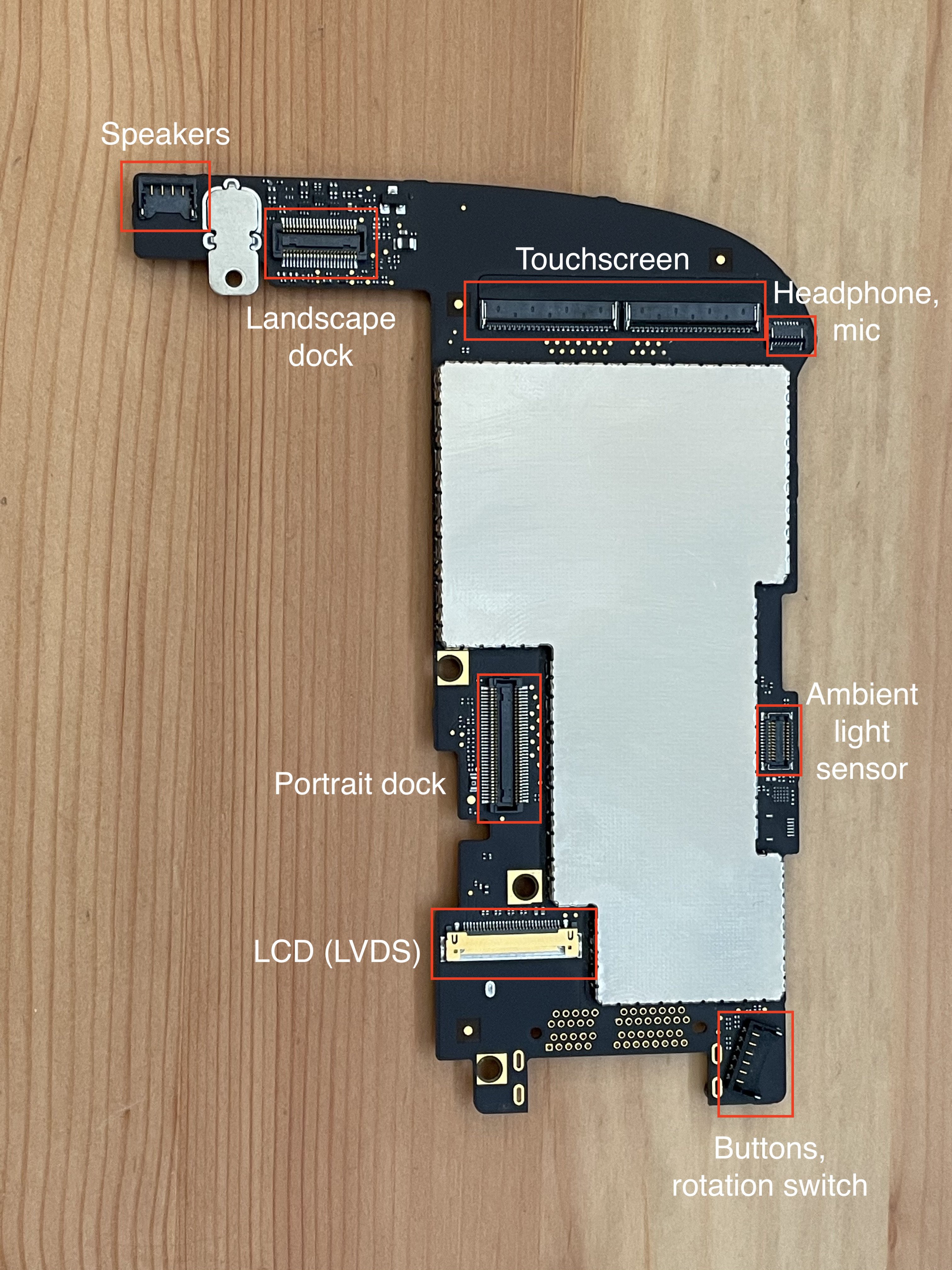
![]()
I haven't decided whether to keep the portrait dock daughterboard, which is a long, narrow PCB that goes from the connector labeled as "Portrait dock" above, and ends with the 30-pin connector at the bottom of the iPad. It also has the iPad's wifi/BT controller on it - a BCM4329 connected via SDIO, which does appear to be supported in Linux. I think Apple put the wifi/BT controller here because it minimizes the antenna cable lengths -- one is behind the screen in the bottom-left, one is behind the Apple logo on the back. If I keep it, I won't have to deal with anything RF. It might also be sorta fun to keep 30-pin connector compatibility, so I can use original iPad/iPod accessories to break out component video (which the RPi CM4 has, for some reason), line-out, USB, etc. On the other hand, scrapping the 30-pin connector and putting in some USB-C ports instead would open up some more modern possibilities: HDMI/DP output, USB PD, USB 3 speeds, Thunderbolt... Plus I wouldn't have to scrounge around eBay for obsolete dongles.
Anyway, for now I've started designing a circuit with a codec from TI, a pair of class-D amplifiers for the speakers (also from TI), and some analog switches to allow me to route the line-out signal elsewhere. The codec also has ADCs that I can use for the internal and external (headphone) microphones.
TI has some codecs that have almost everything I want: built-in class D amplifiers for speakers, built-in headphone amplifiers, additional line-out pins, but most of the good ones are WLCSP, meaning 0.5mm BGA or smaller, meaning expensive PCBs. I've opted for one of the QFN packages, which I should be able to lay out with the capabilities of cheap PCB manufacturers.
-
The big scary touchscreen connectors
02/03/2021 at 07:59 • 0 commentsThe biggest unknown to me when starting this project was how I was going to interface with the touchscreen. In general, all the other connectors on the logic board are some sort of standard signaling scheme, like analog audio, I2C, USB, SDIO, or LVDS. I've never worked with a capacitive touchscreen before, so I had no clue where to start. (I've never worked with LVDS before either, but I at least have an idea where I'd learn things about it.)
![]()
A lot of my initial research began with the iFixit teardown for the iPad. In addition to information on how to get into the device, they've got all the part numbers for the various chips. They identify the TI CD3240A1 as the touchscreen controller, but my internet searches find nothing helpful about this. Other articles identify the BCM5973 as part of the touchscreen system. I can find distributors willing to sell me the BCM5973, but no datasheets or anything.
Taking a different approach, I looked at what touchscreen controllers are available to buy on Digi-Key, etc. The easiest to buy controller family I found is the Microchip (Atmel) MaxTouch family, such as the MXT1664T3. (There are also some Cypress chips available on Mouser, but the publicly available datasheets for these are really just spec sheets, and lack any useful information on how to use the chips.)
I also stumbled upon this blog post series over at Mike's Mods about trying to reverse-engineer the iPad 3 touchscreen digitizer. Not exactly the same product (for some reason the iPad 1's touchscreen has 102 pins.), but this does a pretty good job of explaining the way capacitive touchscreens work.
Between the maxTouch datasheet and the blog post series linked above, I gained an understanding of how touchscreens work:
There is a set of parallel wires going across the screen, and another set of parallel wires perpendicular to the first set. One set of wires are "transmit" lines, the other are "receive" lines. The controller will drive one transmit line at a time with some sort of AC signal, while measuring how much of this signal is capacitively coupled into each receive line. When a finger is near the intersection of a particular transmit line and a particular receive line, the capacitive coupling between those two lines will be different (less?) than if there is no finger present.
Mike mentioned that he was able to find leaked schematics for the iPad 3, so I googled around for "iPad A1219 schematics" and was able to find a few sketchy-looking sites that have them. (I won't link them here since it's probably a copyright violation to share them.)
From the schematic, we can learn the pinout of the touchscreen. Like the iPad 3, the iPad 1 has a 30x40 grid, with 40 transmit and 30 receive lines. Unlike the iPad 3, though, each receive line is brought back to two separate pins on the FFC connectors. (Except for MT_PANEL_IN<29>, which only ends up in one place for some reason.) 3 ground pins, 40 transmit pins, and 2x30-1 receive pins adds up to 102 pins, split across two 51-pin connectors.
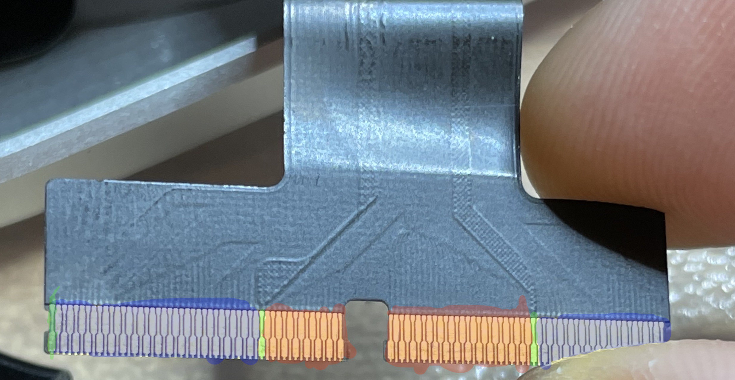
![]()
Here I've highlighted the receive pins in blue, the transmit pins in red, and the ground pins in green.
---------- more ----------In theory, all I need to do is build a board with something like the MXT2952TD wired out to two FFC connectors that will fit this flex cable. The iPad uses Molex 502250-8451 connectors, which are no longer sold, but the 502250-5191 is still available from Arrow and seems compatible.
I started laying out such a board, but then learned that it's expensive (hundreds of dollars) to get boards made with 3 mil tracks / 3 mil space and the 0.15mm minimum drill holes required to fit in between the pads on the mXT2952's 0.5mm-pitch BGA footprint.
I then switched to the automotive version of the controller, the MXT2912TD-A. This is a 0.5mm-pitch LQFP with 176 pins, which is much easier to lay out. (With the downside that it's massive -- 24mm x 24mm, instead of 5x10mm for the 2952.) Then I noticed that the automotive parts aren't available in quantities lower than 40 (at $15/unit, so $600 per lot.) Back to the 2952, and I guess I'll just have to suck it up and spend $300 on PCB manufacturing and hope I don't mess it up.
Ideally, I'd get one board made that does everything, but in order to keep the expensive part small (and avoid having to pay lots of money if I make a mistake in a different part of the circuit), I think I'm going to make a small board with just the touchscreen controller, and put everything else on a different board.
I've put my KiCad files up at https://github.com/EvanKrall/ipad_touchscreen_driver. If you have any feedback, please let me know! I'm still quite new at PCB design.
Put a Raspberry Pi CM4 into an original iPad
Open up a 2010 iPad, remove its logic board, and fabricate a new board based around the Raspberry Pi CM4.