Close
0%
0%

Limrose Compukit 1

Recreation of the Limrose Compukit 1 from 1970.

Similar projects worth following
This is a hardware replica of the Limrose Compukit 1 from 1970. I have a love of straightforward electronics and have always loved the simplicity and board design. Given that it was one of the earliest commercial "digital" computing devices, I find it weird that so little is known about it. I have yet to find the manual online.
The goals of this project (roughly) are:
1. Create a hardware replica of the board. (Design done, Prototype done)
2. Create an add-on board that turns it into the Compukit 1 Deluxe (include 2 more lights and switches). (Design done)
3. Create an SMD version as a business card for fun.
4. Make a few kits to sell in order to get good quality PCBs made.

Side goals:
1. Make Compukit 1 De luxe PCB
2. Make interesting circuits for the Compukit.
- one bit-computer (design done)
- simple games (simple Nim, etc.)

The images of the original come from https://www.earlycomputers.com/cgi-bin/item-report-main.cgi?20110802, https://www.earlycomputers.com/cgi-bin/item-report-main.cgi?20110802, and http://www.vintage-icl-computers.com/icl48i. Other than a few random images, these are the only sources of information I've found on the device. None of them have the manual shared (they only share ad material).

deluxeCK1addon_v1.zip

Kicad files for addon board to turn the Compukit 1 into the deluxe model. Essentially just adds two gates and two LEDs.

Zip Archive - 233.32 kB - 02/16/2021 at 21:54

Download

compukit1deluxe_v1.zip

Kicad files for Compukit 1 Deluxe as a single board.

Zip Archive - 606.97 kB - 02/16/2021 at 21:53

Download

cklogo_new.png

The logo graphic.

Portable Network Graphics (PNG) - 32.10 kB - 02/03/2021 at 22:26

Preview

compukit1_v1.zip

Kicad files for Compukit 1 including schematic and pcb.

Zip Archive - 317.00 kB - 02/03/2021 at 22:24

Download

  • 16 × Diode
  • 15 × 1K Resistor
  • 25 × 10K Resistor
  • 2 × 150 Resistor
  • 16 × NPN Transistor

View all 12 components

  • Custom PCBs from PCBWay

    deftcoyote03/12/2023 at 21:08 0 comments

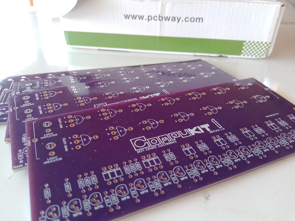
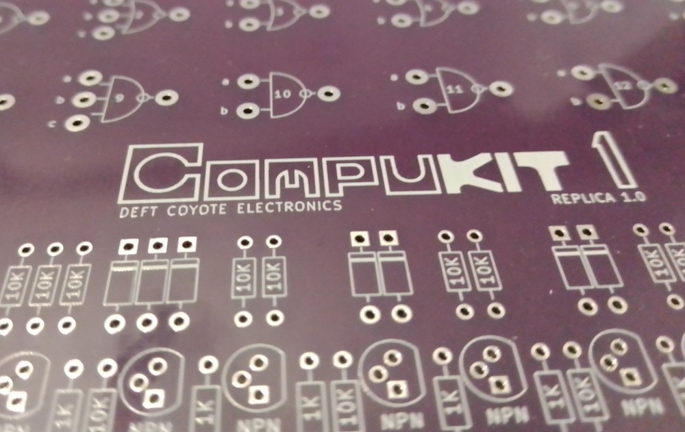
    I'm a few weeks behind on updates! I was offered free custom PCBs from PCBWay over a month ago in order to try out their service (I had never ordered my own PCBs before). The process was easy and I just used the gerber files generated from the Kicad files on the project. I couldn't resist going for the purple boards in order to have something flashy. I got them a few days later and they are beautiful.

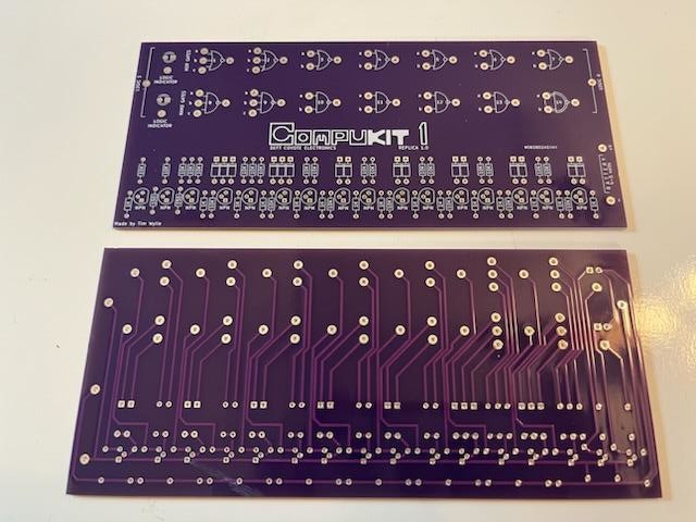
    Here are the back and front together.

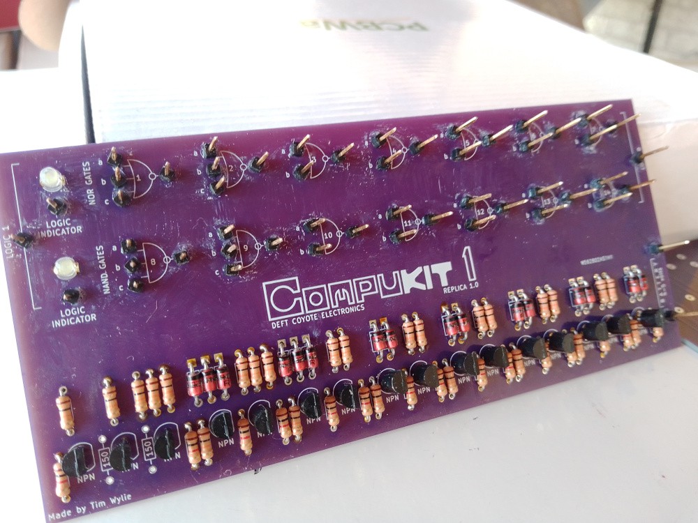
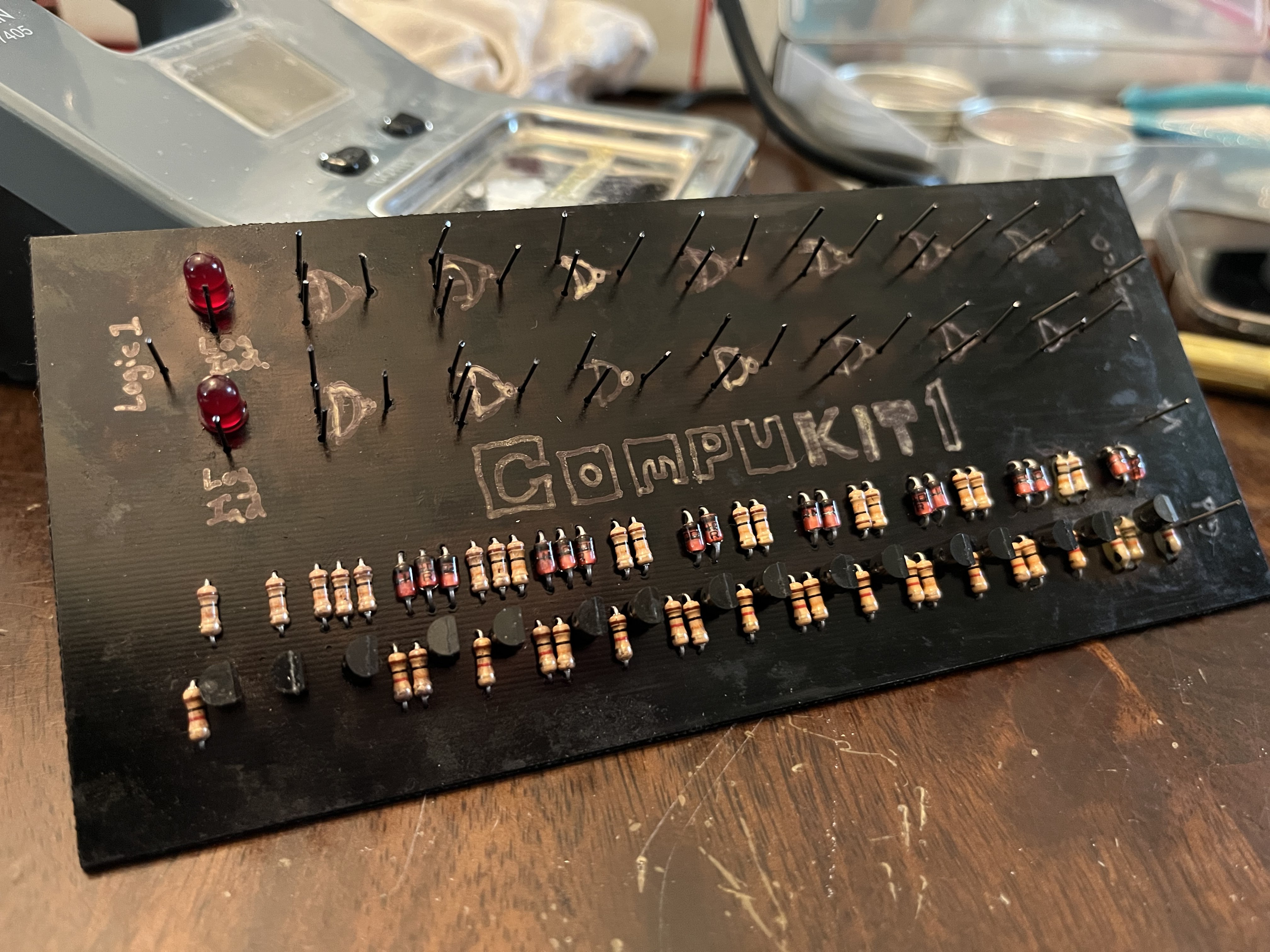
    I had to order the single pin posts, which took a week or so. I was not expecting the vertical alignment of the pins be so difficult. I should have used combined pin mounts to make this easier, but I was trying to stay close to the original design, which were all single posts. You can see the finished board below. In order to ensure I didn't bend the pins after solder, I added a dab of super glue on top. This worked great until I accidentally smeared it over the board. This is why there are white smudges on top. I scrapped off as much as I could. I should have only messed with it after I had finished all the pins. Well, lesson learned.

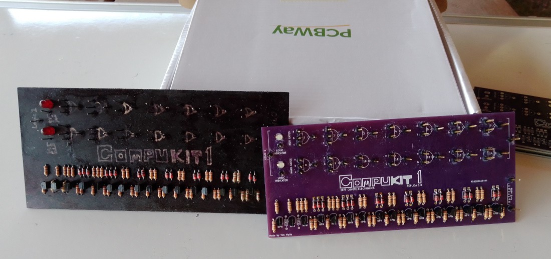
    Here's a picture of the rough prototype and the finished board. Next I'll get a case made and do some testing. 

    I realized one important thing after getting the boards: I didn't include any holes for mounting the PCB in a case. I guess these are the things you lean with experience. I'm going to make a case with a slot design to adjust for this. 

    Within the next few weeks I'll update about the 3D printed case, and some testing to make sure everything is working as expected. This was such a wonderful experience. Thanks again to PCBWay for sponsoring the project and the help throughout the process.

    Finally, a closer look at the center graphic because I want to.

  • Final Prototype

    deftcoyote01/08/2023 at 03:05 0 comments

    I couldn't wait to order pins when the prototype was so close to being done. Rather than wait, I just cut a bunch of pin nails that I had down to size and soldered them on. I also used a paint pen to draw the symbols and labels on. After fixing a few shorts, the board works! I need to mount it in something, and maybe cut the pins shorter (I left them long just in case).

    Once that's done I can make a few simple circuits for testing, but I'm excited to get this rough prototype finished, I still don't have the official manual that came with it, so I can't try the "official" circuits they suggested- whatever they were.

  • Prototype Components

    deftcoyote01/07/2023 at 05:23 0 comments

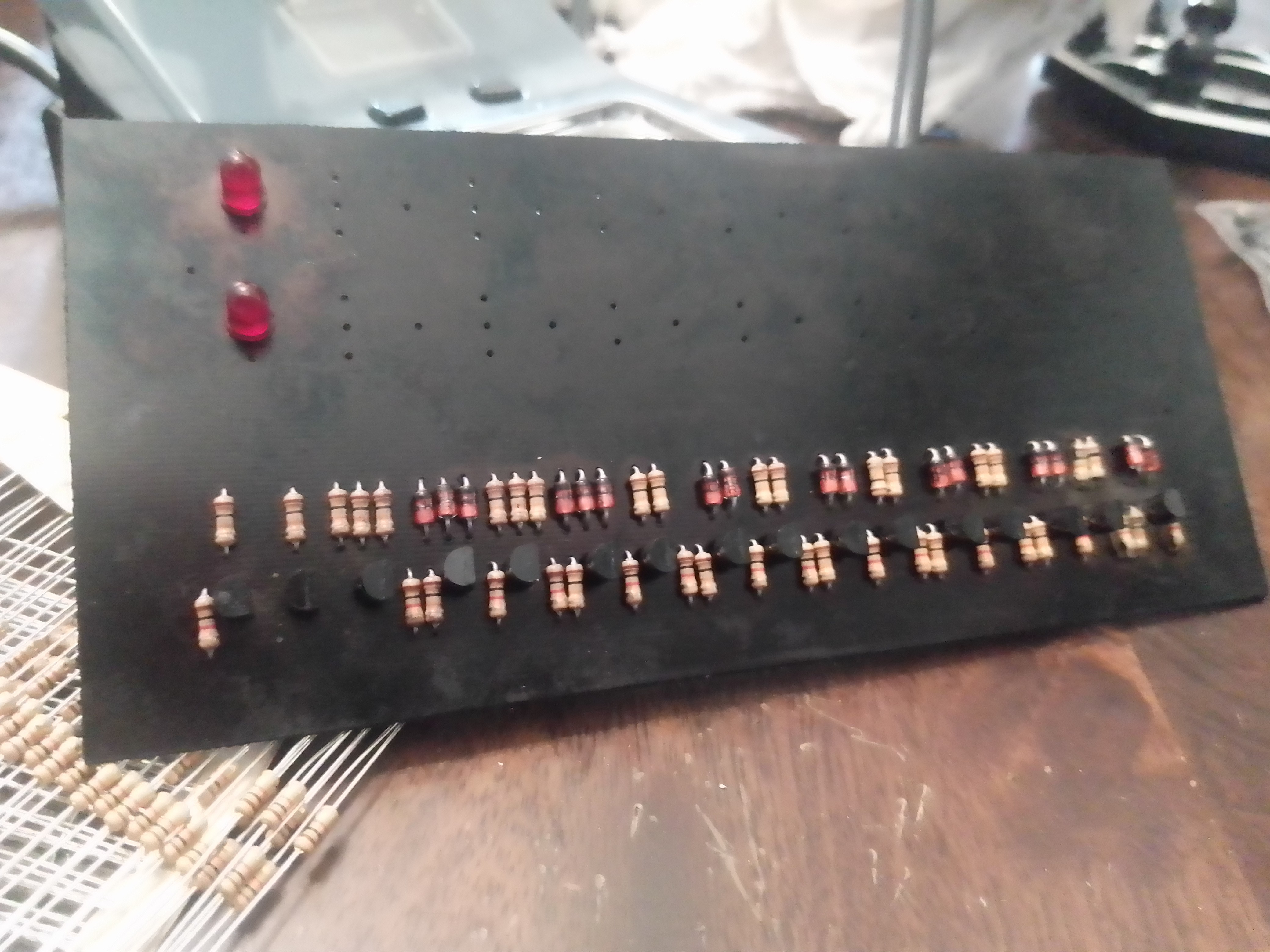
    I did not have enough 10k resistors originally to finish, so I put the project up and ordered some. In the interim, things got pretty busy and I did a lot of other projects. Anyway, I got some new soldering tips, and finally finished soldering the components on. I also colored the board black with a sharpie. I need to get some pins to solder in for the gates, and I'll draw the NAND/NOR symbols on (or get stickers), and do some debugging testing. But for now, here's a fuzzy picture of the board.

    Hopefully I can get the pins fairly soon and I'll give an update then. I originally wanted to order a nice board since they're cheap, but I think I'm happy with just having the etched board.

  • Starting Prototype / LED considerations

    deftcoyote03/08/2021 at 04:30 0 comments

    Well, I double checked some components and wiring, and started soldering the main board together. Unfortunately, I only have a few diodes, so I only soldered a couple of the components to test whether the gates were working correctly. I'm ordering some more.

    Here's the start:


    And you can see some of the testing.


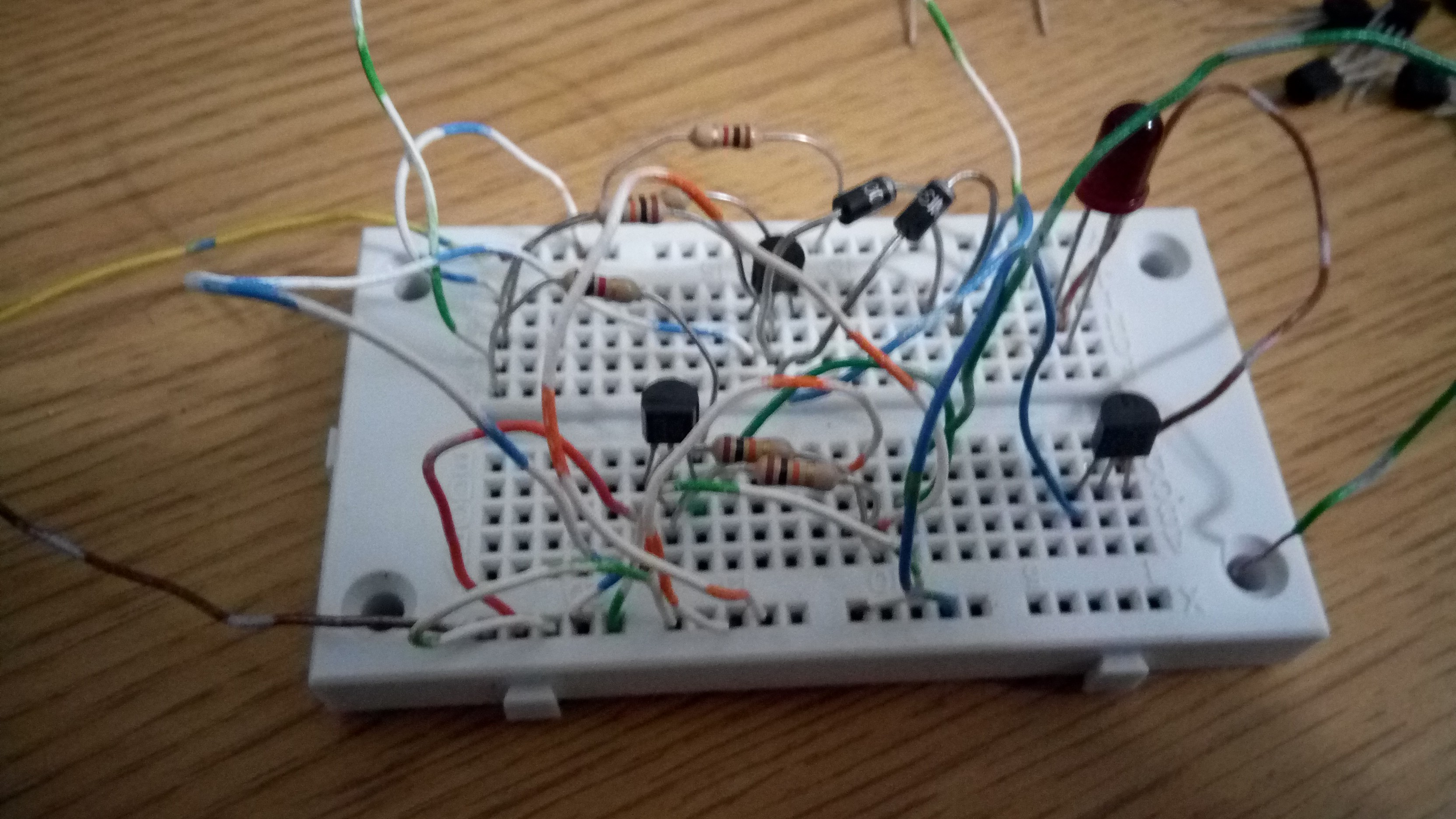
    I was expecting this issue with the LEDs, but it's still annoying. The original Compukit used bulbs, and the transistor expected voltage on the base to connect it to ground for it to light up. It also had a 150 O resistor straight to ground. With an LED, it stays lit up unless you put > 1 M resistor there. The best plan, I believe, is to remove the two 150 O resistors altogether.

    Also, the 10K resistor on the base (the logic indicator allowing the LED to light up), seems to be too great. Although, I was testing with around 3.5 volts. So I may reduce that resistor as well, but I need to test a bit more.

    I will update the board and schematic once I determine the best values for the LEDs, and I think it may be possible to simply remove the two grounding resistors. The only problem with this is that there's no resistor coupled with the LED going to ground if you directly touch the logic 1 probe to the logic indicator, so one might need to be added between the LED and the transistor rather than it's current design.

  • Compukit 1 De luxe Addon Board

    deftcoyote02/16/2021 at 21:51 0 comments

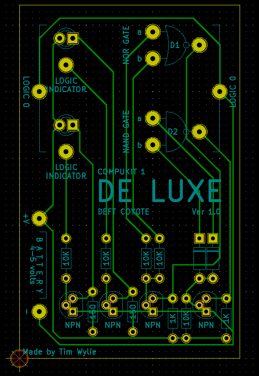
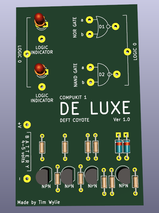
    I'm feeling motivated to ignore work I should be doing. It seemed silly to not just quickly create the addon board to turn the Compukit 1 into the Compukit 1 De luxe. It's designed to mount the board through the Logic 0 and two battery terminals. 3 screws or pins. Anyway, once I get the other board done, I'll try prototyping this as well. The kicad files have been added. Here are the images.


    I like the look of the little board to just attach to the larger one. I think now I can just focus on the applications of the boards and actually making them.

  • Compukit 1 DE LUXE

    deftcoyote02/16/2021 at 18:51 0 comments

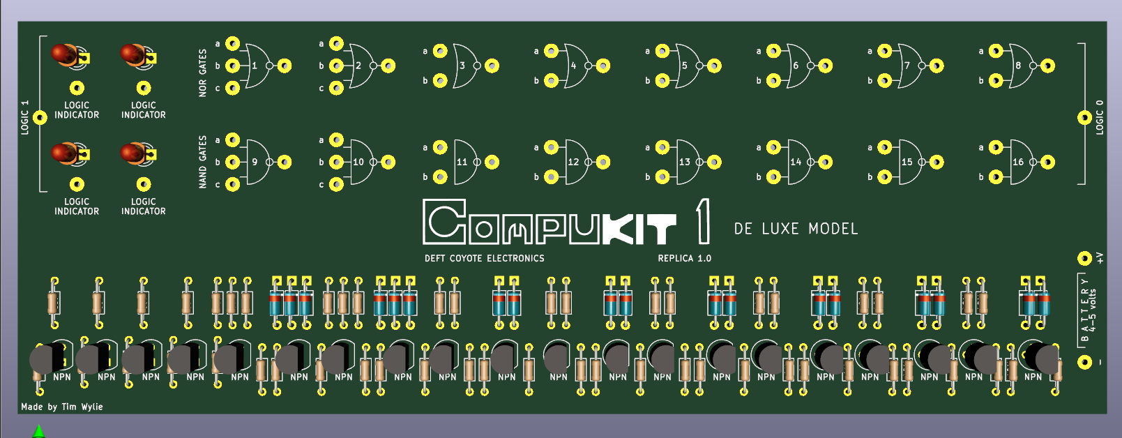
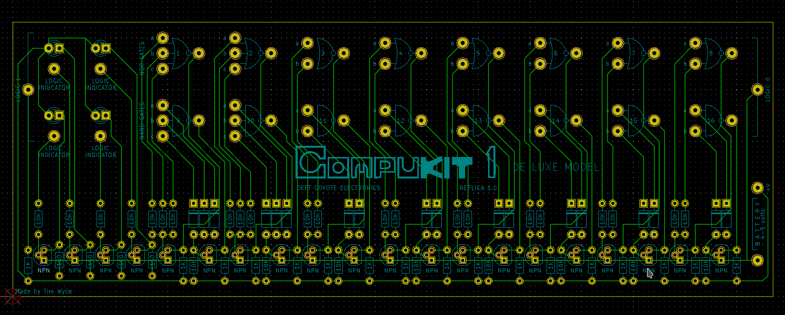
    On a whim, I added the two extra gates and two LEDs into a single board. I still want to have the Compukit 1 normal with a small addon board instead of actually making this version, but I figured I might as well make this in case anyone wants it. The board ratio is too long in my opinion. I think putting the LEDs and the transistors/resistors for them on top would make the board a little more square.

    Anyway, here's the 3D rendering.

    I might also add in the logic table like the original had. I did keep the space in deluxe, though. That is clearly necessary for authenticity.

    I added the additional needed components to the Component section with a "for Deluxe" after the component to identify them as separate.
  • Turning the Compukit 1 into a Computer

    deftcoyote02/14/2021 at 23:23 0 comments

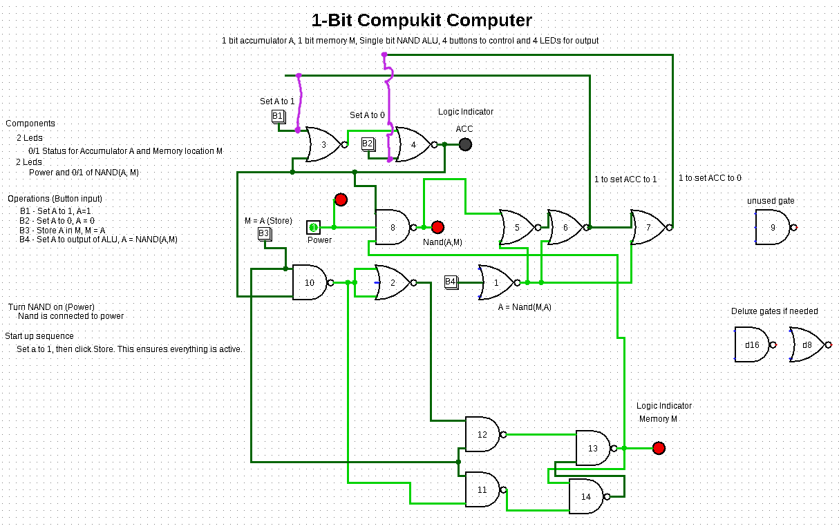
    A couple of places have noted that the Compukit 1 could qualify as one of the earliest home computing devices available to the public. This definitely depends on what you count as a computer. I've been playing in logism with the gates and have come up with a legitimate computer that can be made using the Compukit 1. My design shows 4 LEDs, but you can ignore the 2nd two if wanted. It only requires adding 4 switches (or buttons). The logism diagram is below. The gates are labeled the same as on the Compukit.

    Computer description: 1-bit Accumulator A(via SR flip-flop), 1-bit memory M(via gated SR flip-flop), 1-bit ALU that implements a NAND between A and M. Since NAND is universal, all computable functions can be implemented (with more memory).

    The input:
      Button 1: Set A to 1, A=1
      Button 2: Set A to 0, A=0
      Button 3: Store value of A in M, M = A
      Button 4: Set A equal to the NAND of A and M. A = NAND(A, M)

    Output:
      LED 1: 0/1 status of accumulator A
      LED 2: 0/1 status of Memory M
      LED 3: Power (optional)
      LED 4: NAND(A, M) (optional)

    The purple lines set A to the output of the ALU, but due to the way the buttons work, it messes up the simulation, however, I don't think this will be an issue in the real hardware. Also, to start, it's necessary to turn the power on, which holds the NAND line with a positive input, then set A and M just to get initial values on the lines. If anyone has any thoughts, I'd appreciate it.

    There is one gate not used, and I included 2 additional gates in case I wanted to use the deluxe model of the Compukit 1 instead, which had 16 rather than 14 gates.

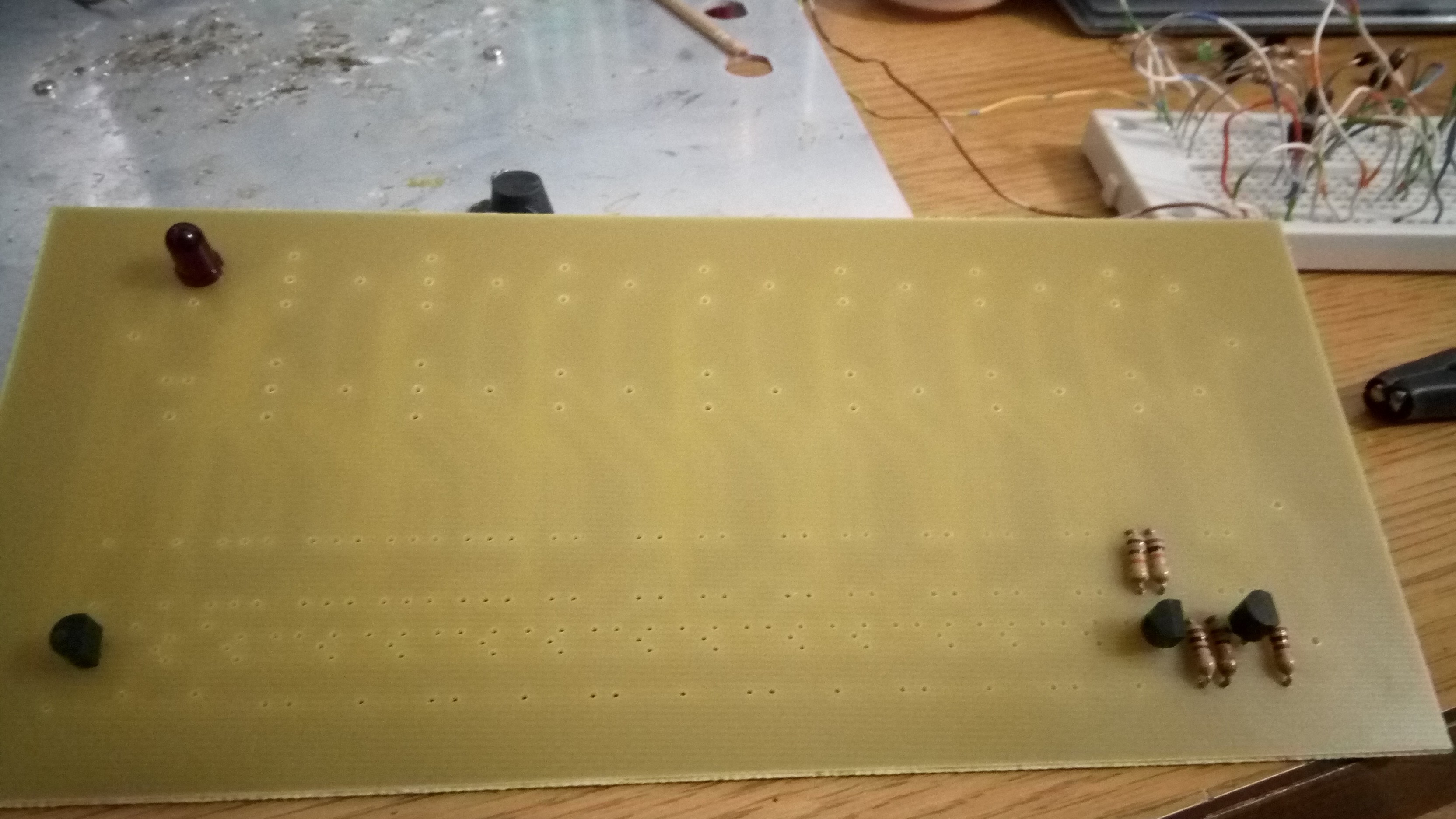
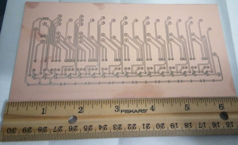
    In relation to the hardware, I had a prototype board printed after widening the tracks to .6 (instead of .25 that's in the uploaded kicad files). Unfortunately, they routed the tracks as if they were meant to be on top (so the board is mirrored), but another one has been printed and I'll pick it up this week. Here's a picture of the mirrored one.

  • Initial Status

    deftcoyote02/03/2021 at 22:06 0 comments

    Project goal 1 is complete for the most part. The circuit and pcb were done in Kicad, and the compukit logo was done in inkscape. I have not physically tested specific components yet. Thus, I still need to decide what diodes to use, and I might need to modify the two resistors connected with the LEDs. The original compukit had small lamps. I left the same resistor and plan to use 1.6 mm LEDs, however, I haven't done the math or tested this, so it may need some adjustment.

    I was considering ordering a single PCB first to make some of the breadboarding easier, but haven't decided if this is a good idea or not. I also haven't decided on the exact transistors to use and was planning on just the cheapest standard size available. The whole board is running on 4 to 5 volts.

    I would appreciate any input.

View all 8 project logs

Enjoy this project?

Share

Discussions

Similar Projects

Does this project spark your interest?

Become a member to follow this project and never miss any updates