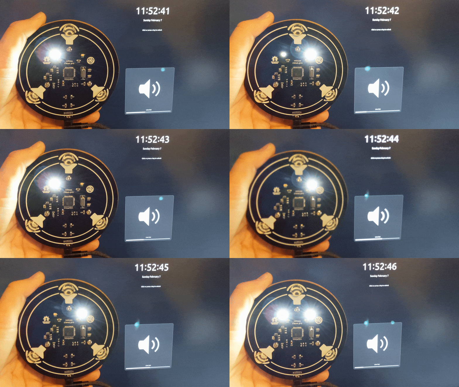
Here I incorporated some learnings from the intervening years. Upgrades from the first revision included:
- Schematic and PCB layout completely redone but using KiCad instead of Eagle.
- Microcontroller changed from an AT90usb162 AVR to an ATmega32U4.
- Remove the serial Tx/Rx connector.
- Remove the reset tact-switch.
- Use smd components instead of through-hole.
- Connect with a USB type C connector instead of a USB type B.
- Have the PCB fabricated (JLCPCB) instead of the home-made copper-etch method.
- A couple of LEDs on the bottom of the PCB purely to visualise the gray code (Rev 1 had LEDs but they only barely shone through etched sections of the PCB).
- Generally improved and cleaner code (still using the LUFA library).
In action. The LEDs are a fun way of visualising the gray code.

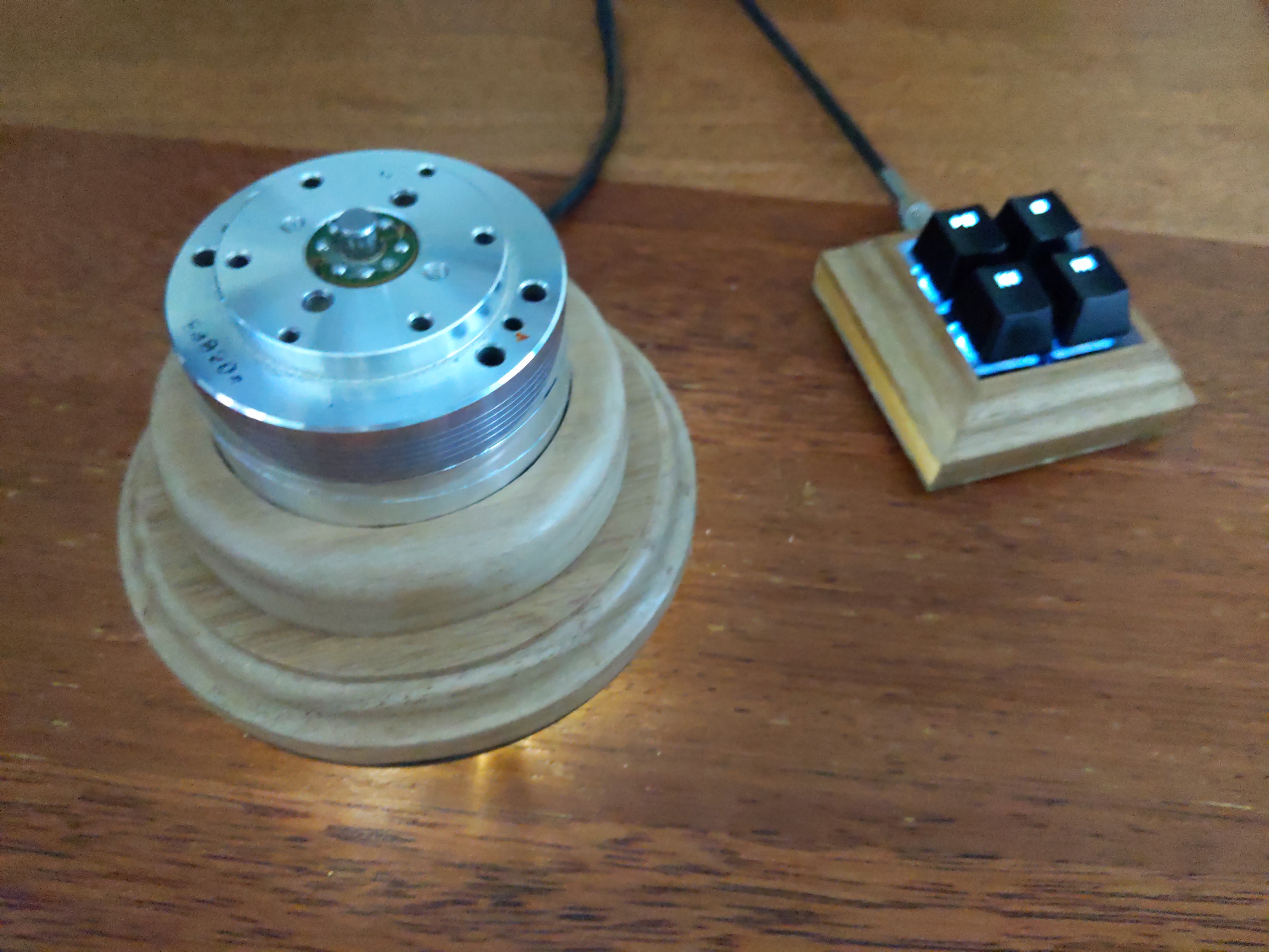
Here it is next to another project (macr0).

 clewsy
Discussions
Become a Hackaday.io Member
Create an account to leave a comment. Already have an account? Log In.