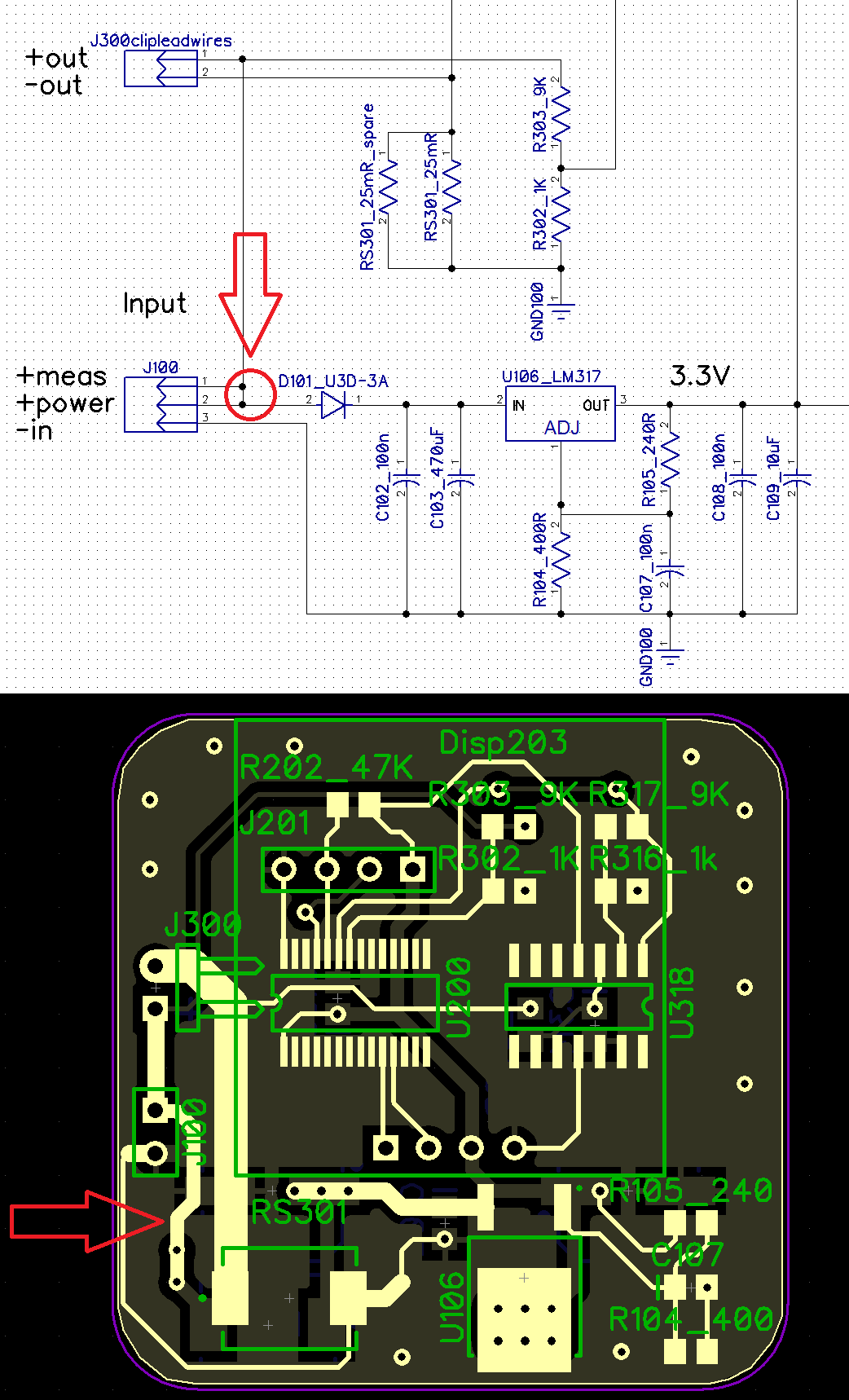
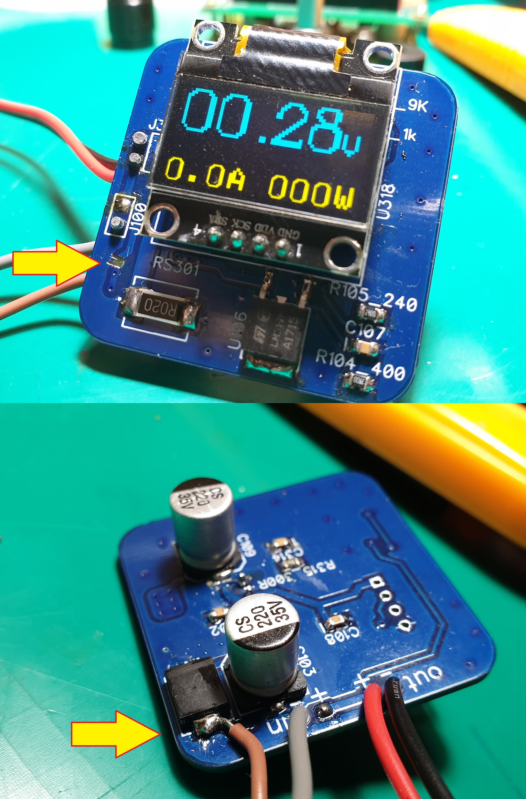
If you watch the video, you will understand that this meter has a jumper trace on the board and this allows it to be connected in two ways. If the jumper is present, the meter will be powered from the measured voltage. This automatically means that it will only measure voltages from 6V to 35V. If the user wants to disconnect the meter power from the measured power, that can be done by removing this link right here:

You have to simply scrape off this trace or a length of 2mm out of it and interrupt its continuity. You can then solder an input power wire to the input terminal of the D101 diode on the other side of the board. This new wire will be the separate power input for the meter. In this way, the meter will measure voltages from 0 to 35V present on the J300 connector.

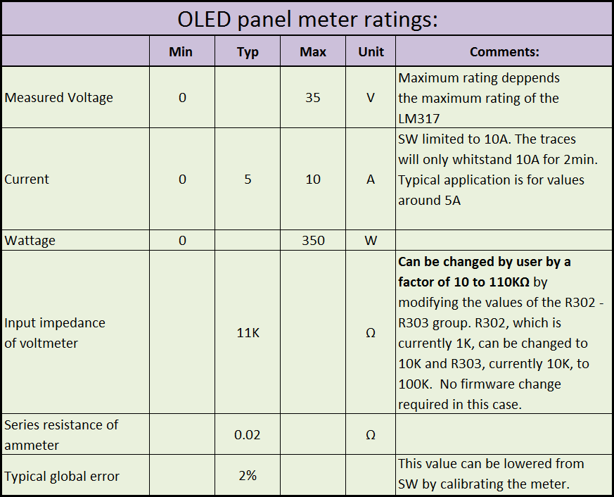
As for the maximum ratings this meter would be able to measure the followings:

 Marius Taciuc
Discussions
Become a Hackaday.io Member
Create an account to leave a comment. Already have an account? Log In.