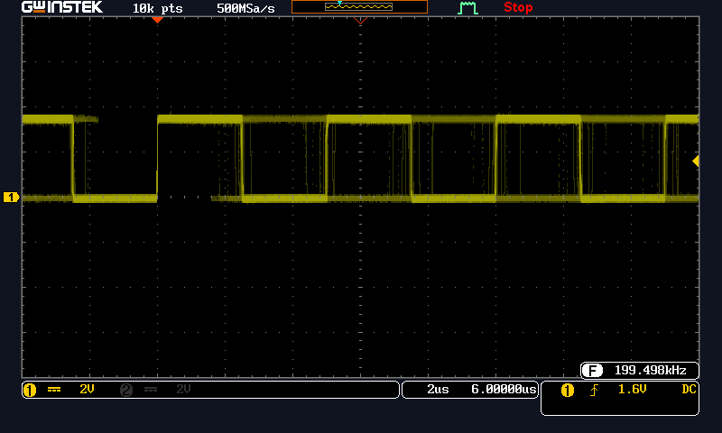
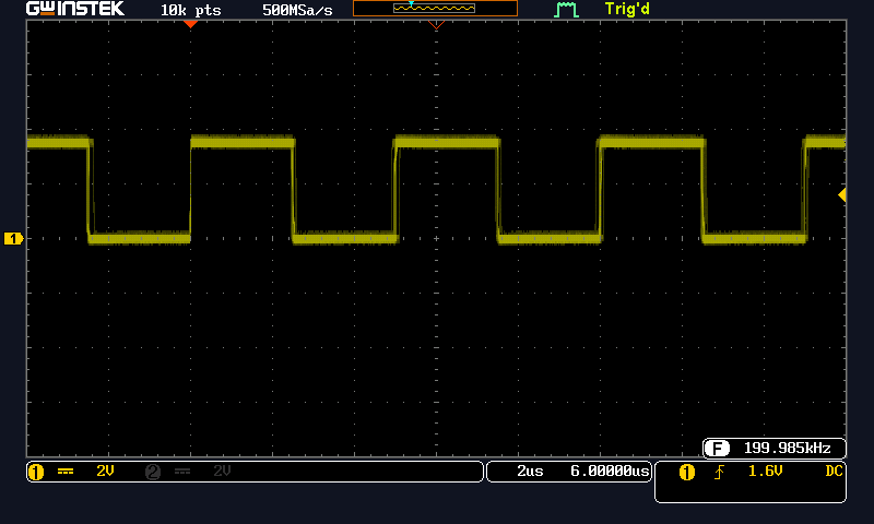
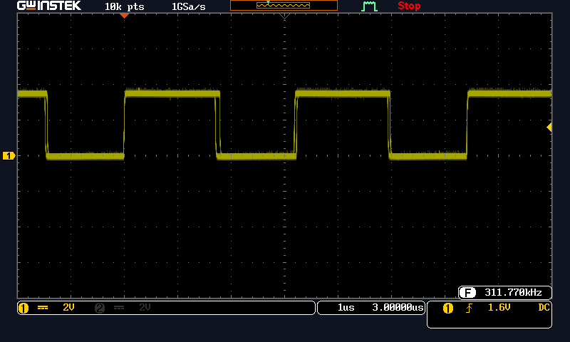
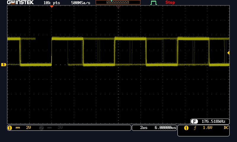
Experiments using Arduino compatible boards to generate signals 100kHz to 2MHz
To make the experience fit your profile, pick a username and tell us what interests you.
We found and based on your interests.
Many Microchip PIC16F family parts have a numerically controlled oscillator (NCO) peripheral. Will this work to generate signal for testing IF filters?
The clock is still 16MHz divided by something. The NCO peripheral has a state machine that dithers between 2 divisors. This gives a blended frequency. A frequency counter can't see the dither. I'm not sure about tuned filters. The NCO state machine consists of an accumulator and full adder. A fixed integer is added to the accumulator every cycle. The adder overflow generates the tick of the frequency output.
The NCO in PIC16F parts has a 20 bit accumulator and 16MHz clock. For 50% duty, the overflow toggles the output. Output frequency is half when in 50% mode. So that means target overflow frequency is 910kHz for my application. That's a divisor of 17 or 18 or somewhere in between. The dithering will have to do it's job at these frequencies. The NCO output will have some spectrum spreading. The signal won't be a sharp line in frequency domain. This could make filter testing more difficult. It's still worth trying. It seems like a great solution, if it works.
Microchip has several useful application notes on how to use NCO. Most of these are related to precise PWM or generating a data clock. I plan to get a Microchip development board for testing. https://www.microchip.com/developmenttools/ProductDetails/DM164141 $12.25 is a reasonable price for a dev board.
The dev board is running a PIC16F18345 processor. This has NCO peripheral and a 32 MHZ internal clock. It includes a USB to PIC16 programmer. I'll have to figure out what toolchain to use for Linux. This isn't Arduino, but PIC isn't difficult.
gputils https://gputils.sourceforge.io/ says it supports PIC16F18345
Next steps: Try a knock-off pro mini board running ATMEGA328P. This board is a 3.3V, so clock is only 8MHz. This is worst case for trying to make signals above 100kHz.
- The tone() function was awful. The square waves have periodic jitters at any frequency tried. It seems the default tone() function is software driven.
- There are timer libraries that use one of the 3 timers in the ATMEGA328P chip. I tried one that uses Timer2. This worked great. No jitter, since it's running the peripheral timer. This timer hardware is locked to specific pins, OC2A and OC2B. These map out to pins 15 and 1 of the chip. These show up as D11 and D3 in Arduino digital I/O numbering.
- Timer 2 is only 8 bits, so that limits resolution. The function is setup to make square waves. This seems to run in "Phase Correct PWM Mode" This is described on the ATMEGA328P data sheet. Anyway, the divisor resolution is limited because it is counting up and down to make a symmetrical square wave. The count up and count down is effectively a divide by 2 from the peripheral clock. The Timer 2 peripheral and this library was able to make a square wave as high as 500kHz in 1 microsecond steps.
- Now the goal is to make 455kHz in 1kHz steps. For example consider 455kHz and 456kHz. The period difference between these frequencies is only 4.8 nanoseconds. To generate these frequencies by direct division, the clock would need a period of 4.8 nanoseconds. This would require a peripheral clock over 200MHz. Clearly a simple ATMEGA won't do this. The ARM M0 won't do this either. Something else is needed. A FRACTIONAL divider is needed to get these in between frequencies.
This could be:
More information to follow.
I've been experimenting with old radios lately. The old analog signal generator works, but it's got issues. The dial calibration isn't good and the 455kHz sweep output is crummy. The box is bulky and requires AC power. Time for something better. Get an ARM M0 board and generate the desired signal on a digital output pin. Should be easy, right? Well, all plans encounter technical issues.
Let's start with an Adafruit ItsyBitsy M0 Express board. https://www.adafruit.com/product/3727 That should be faster than the ATMEGA boards. This board runs an ATSAMD21 at 48MHz. Seems like a good start to divide down to the desired frequencies. This board uses the internal oscillator, so it won't be accurate like a crystal osc. It should be better than +/-2% dial calibration on the analog signal generator.
void setup() {
// put your setup code here, to run once:
tone(7, 200000);
}
That's an unstable mess. There's over 500ns of jitter.
OK. That's better. The USB port firmware must be interrupting the tone() function. Lesson learned: Disconnect the computer for a stable output. Let's try using the USB A port on the oscilloscope for power. No, the output is unstable again. Let's try power from a cheap charger. That's stable again. I'm going to use battery power since it gives the cleanest results.
Try tone(7, 250000); Output was stable 250.0 kHz.
Try tone(7, 300000); Output was stable 300 kHz, without much jitter.
Above 300kHz is were things get strange.
tone(7, 301000) generated 303.8 kHz. Setting 302000 or 303000 also generated 303.8 kHz. The tone() function is likely using an integer divider from the peripheral clock. The divider resolution is not fine at these higher output frequencies. This causes coarse steps in output frequency. Maybe the tone() function can be improved, but this isn't going to replace an analog signal generator at 455 kHz.
Setting 304000, 305000 or 307000 all generated 307.7 kHz.
Setting tone(7, 308000); generated 311.7 kHz with some edge jitter.
Then the board stopped responding to the uploader in the Arduino IDE. The square wave signal continued, but new code could not be written. This may be an on-chip issue or a bug in the library. The USB port was not functional. The IDE reported "no device found on ttyACM0". Fortunately this board has a nice USB bootloader. The following sequence worked to restore normal operation:
I did this several times to confirm the tone() settings that caused the port to lockup. Let's try a higher frequency.
Setting tone(7, 350000); generated 176.6 kHz with bad jitter.
Setting tone(7, 390000); generated 196.7 kHz with some edge jitter.
In summary
Create an account to leave a comment. Already have an account? Log In.
Become a member to follow this project and never miss any updates