Technologies
Technologies used, in addition to the HC-SR04, include:
- Control of an addressable (WS2812B) LED strip via the FastLED library
- Sensing the ambient air temperature to compute an accurate speed of sound for distance measurement
- WiFi connection to the home network for control
- Setting the “target” parking distance via pushbutton
- Setup of parameters by web application
- Web application implemented an approach where the characteristics of the set of control parameters were defined in a JSON file
- Websocket interface for delivery of parameters
- A telnet interface for debugging and/or monitoring the status of the unit from within the home network
- Supported ArduinoOTA for code downloads over the network
- mDNS for network address discovery
- Parameters retained in the ESP32 using nonvolatile storage in the ESP32
- A real-time clock, synchronized to an NTP time server, to turn off the unit during off-hours
- Printed circuit board designed to fit within a standard plastic enclosure
Design Approach:
The design was inspired by an article in Makerguides here. I added to the basic distance-measurement functionality for this application by:
- Driving an LED strip based on distance to target, to give a visual indication on approach
- Using a web interface to set up various parameters
- Shutting down measurement-taking during specified hours of the day
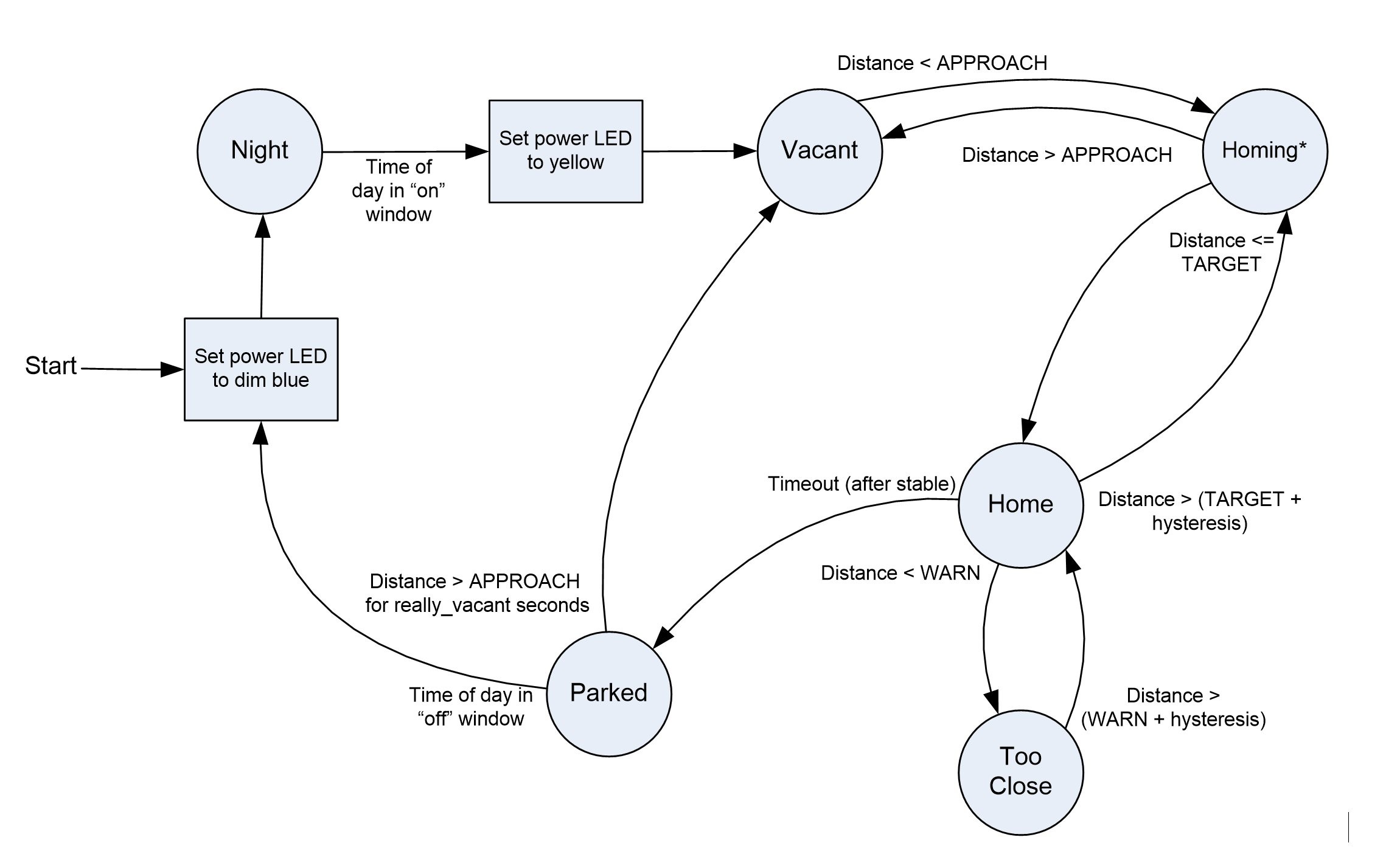
- Implementing a state machine to manage behavior

As shown in the diagram, there are six states:
- Night: quiescent state where measurement-taking is paused due to time of day being outside of operating hours
- Vacant: the state that is entered when the vehicle is moved away from the parking space
- Homing: in this state, the vehicle is approaching the target distance and the unit indicates on the LED display closeness to target
- Home: the vehicle has reached the target distance and has not overshot
- TooClose: the state that is entered if the distance to the sensor is less than a set level
- Parked: this state is achieved after reaching Home state, following a set timeout
Once the Parked state is entered, that state remains active until measurements indicate the vehicle is no longer parked nearby, and a certain time has passed. This state ensures that the LED display is stable (e.g. the lights do not blink, or the TooClose state is not entered) due to people walking between the car and the sensor.
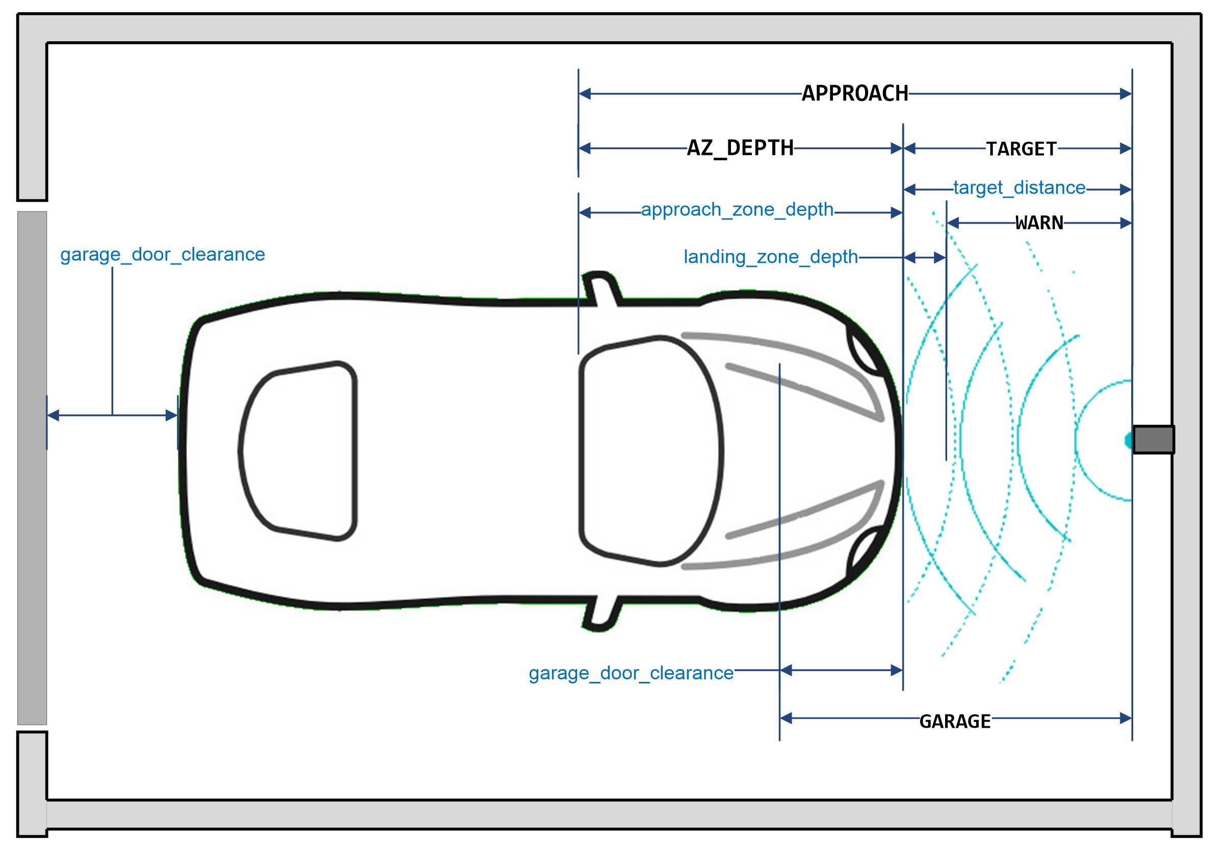
Parameters driving the state transitions are illustrated in the following figure:

The lower-case labels correspond to parameter names in the code. These correspond directly with values specified by the user in the web interface for determining the desired behavior. All parameters are specified in inches, with resolution of 0.1 inch:
target_distance: the distance from the sensor that represents the optimum location for the parked vehicle.
approach_zone_depth: the distance over which the driver will be guided by the LEDs to reach the target.
landing_zone_depth: the depth of the area that is considered OK for the car to be safely parked.
garage_door_clearance: the distance from the rear of the vehicle to the garage door, when the vehicle is parked at the target distance.
The above parameters are delivered via Websockets as integer numbers, in units of tenths of an inch.
The uppercase labels (APPROACH, AZ_DEPTH, TARGET, WARN, GARAGE) are derived from the user settable parameters, and for clarity are used in the state-change calculations. These numbers, as used in the code, are floating point numbers in units of one inch, and are derived from the parameters listed above by dividing by 10.0.
APPROACH: when the vehicle reaches this distance from the sensor, the sample rate for depth measurements is increased (for faster response), and the display changes to a “ready” condition. During the vehicle approach toward the target distance, the top LED is illuminated white, and the bottom LED is illuminated red until the rear end of the vehicle has cleared the garage door.
AZ_DEPTH: this is the range over which the display is actively notifying the driver of the approach to the target.
TARGET: The distance from the sensor that is the target location for a perfect parking job.
WARN: this is the distance from the sensor that, if reached, would trigger a warning display. In the current implementation, the warning is all-red LEDs flashing.
GARAGE: this value, also specified in inches with resolution of 0.1 inch, specifies how much clearance the rear end of the vehicle has with respect to the garage door, when the car is parked at the TARGET location.
A small amount of hysteresis is included to avoid jitter at the transitions. About one inch seemed to work. The parameter is adjustable via the web interface.
Using the HC-SR04:
Using the HC-SR04 unit it was discovered that, even when the object in front of the sensor was stable, occasionally the sensor would output a clearly invalid measurement. For this project, it was desirable to eliminate the effects of such erroneous measurements, for example to avoid display jitter.
Two methods were used to address the problem. First, measurements were placed into a ring buffer (circular queue) so that a running average could be computed. Second, when collecting measurements, individual ones that were found to be more than X percentage above or below the running average were tossed out. The value of X was adjustable, again by a web interface.
Web Interface:
For all of the different ESP32 projects I have built so far, it has been helpful to provide a user interface whereby various operating parameters could be set, and adjusted over time as needed. A general approach was developed, involving:
- A browser-based user interface written in (of course) Javascript and HTML/CSS.
- Use of Websockets to communicate between the project and the browser.
- The ESP32 discovers and connects to the home network in station mode, sets up an mDNS identifier for TCP/IP, and then opens a WebSocket interface.
- Parameters are represented by an array of up to 30 unsigned 32-bit integers.
- The web application uses the mDNS ID to establish a WebSocket connection, then queries the project to retrieve the values of all parameters.
- The ESP32 saves all parameters in nonvolatile storage (NVS).
- Changes to any parameter are delivered immediately via the Websocket interface and saved in the ESP32 in NVS.
- The set of parameters and definitions for the project are defined in a JSON document opened by the web application.
Note: because it loads a local JSON file, the web application must be served from a web server on your network rather than being executed as a file on the local computer (that is, unless you run the browser with “same origin policy” disabled). Otherwise you might see this kind of error in the JavaScript console:
Access to XMLHttpRequest at 'file:///C:/Users/ … /projectName.json' from origin 'null'
has been blocked by CORS policy: Cross origin requests are only supported for protocol
schemes: http, data, chrome, chrome-extension, chrome-untrusted, https
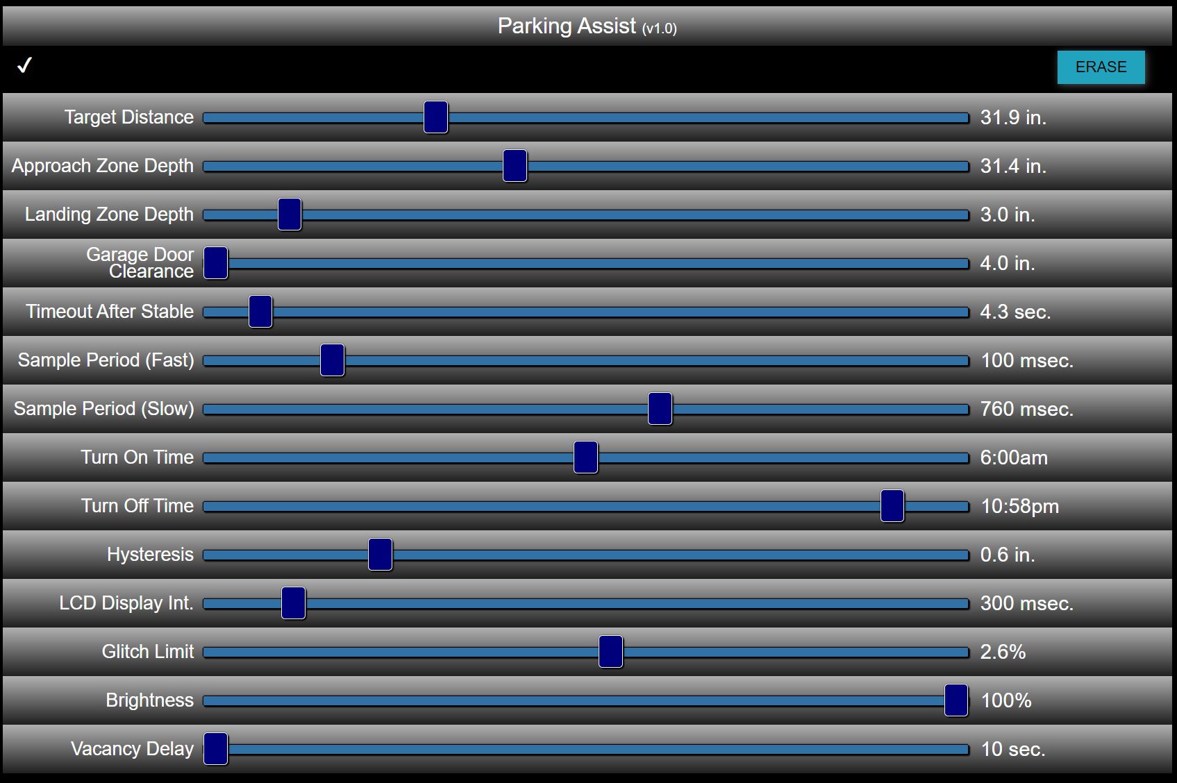
The JSON document, in addition to defining the name of the project (for the web page title), version number, and mDNS name, defines a number of operating parameters. Operating parameters can be values representable by range sliders, Boolean flags (represented by checkboxes), or colors established by “color picker” interface. The web interface for the present project did not utilize any checkboxes or color pickers and is shown here:

The checkmark in the upper left indicates connectivity to the project. The “ERASE” button in the upper left is used to command the project to erase NVS, if needed.
The JSON document defines a number of characteristics of each range slider, including:
- The name (label on left side)
- The minimum and maximum values of the slider.
- The step size
- A simple units label, a function to be used to display the value, or both. Some example functions:
- percent – displays the slider as a whole percentage, where zero is all the way to the left and 100 is all the way to the right.
- percentTenths – displayed as percent as above, but as a floating point number with one digit to the right of the decimal
- tenths – displays the value of the slider, but divided by 10.
- NVS-related functionality including initialization, saving and restoring parameters
- Some helpful utility functions
- mDNS-related functionality
- WiFi connection functions, including reconnection upon lost connection
- Over-the-air (OTA) code download functionality
- WebSockets functionality supporting the parameter array approach
As an example of the latter, the time of day parameters are represented as a number of minutes since midnight, so a parameter that would represent midnight to noon would be specified with a range that goes from zero to 12 * 60 = 360. The name of that display function is “timeOfDay.” Other example display functions are:
- percent – displays the slider as a whole percentage, where zero is all the way to the left and 100 is all the way to the right.
- percentTenths – displayed as percent as above, but as a floating point number with one digit to the right of the decimal
- tenths – displays the value of the slider, but divided by 10.
Other functions can be easily written as needed.
CSS can be included in the JSON definition of any range slider, to provide, for example, a horizontal bar or extra space associated with a given slider.
A link to the JSON document that produced the user interface above is here,.
ESP32 Code:
The code was written in C++ using the PlatformIO development environment running in Visual Studio Code. Source code is archived in Github here..
There are four main files in the source:
- main.css – the main program, including setup() and loop().
- main.h – a header file defining some project-related items used by the project.css file, and defining the array of parameters used.
- project.css – code implementing functions common to many projects, including:
- project.h – header file for the project, providing procedure declarations and definition of a Ring buffer class.
Library dependencies are:
- adafruit/Adafruit Unified Sensor, version 1.1.4 or above
- adafruit/DHT sensor library version 1.4.1 or above
- arduino-libraries/NTPClient version 3.1.0 or above
- m5ez/ezTime version 0.8.3 or above
- fastled/FastLED version 3.4.0
Printed Circuit Board:
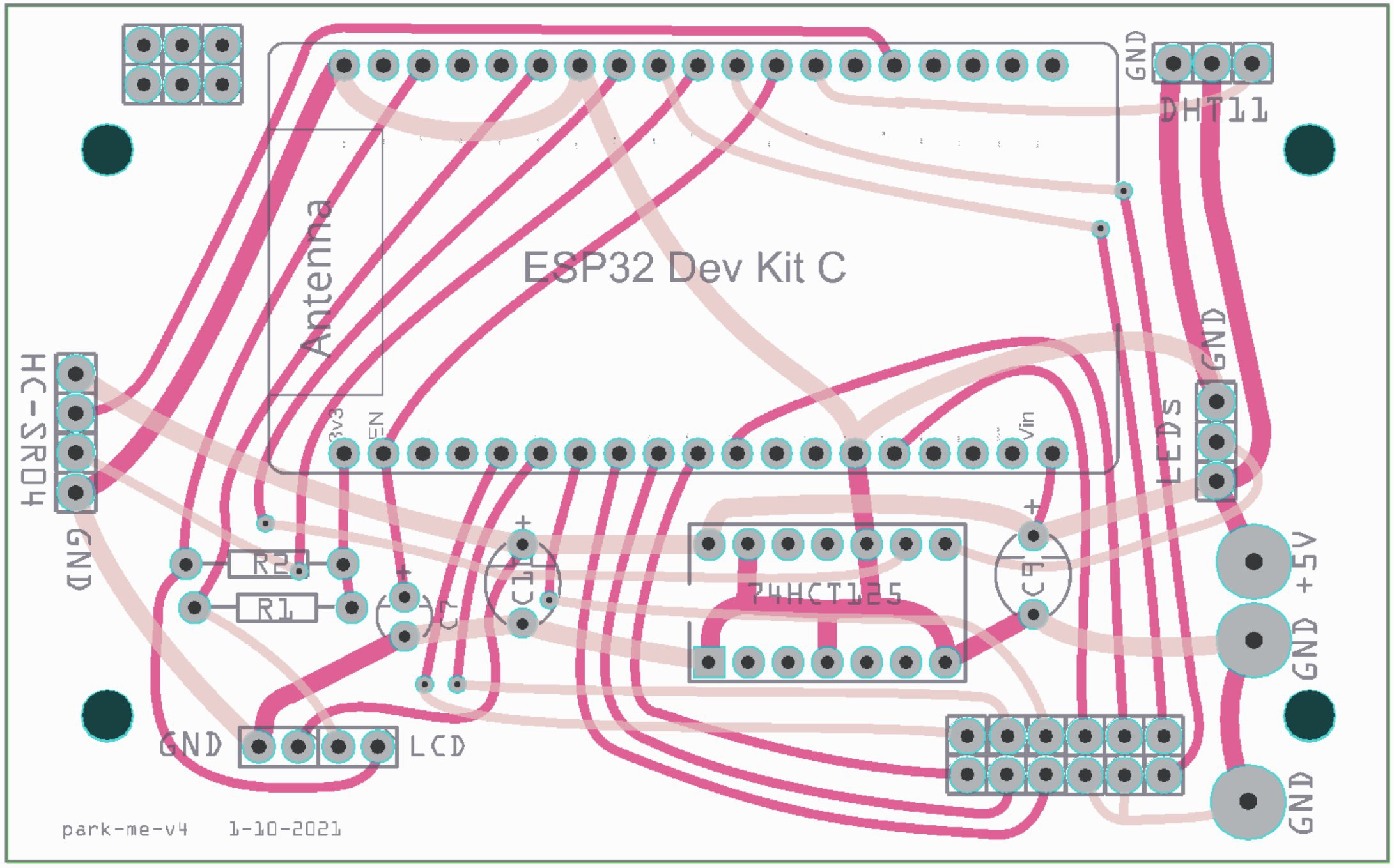
The Fritzing (BETA version 0.9.3) program was used to create a PCB design, pictured here:

Extended Gerber (RS-274X) files were created and delivered to a PC fab house, PCBWay (pcbway.com), which delivered 10 boards in under one week at a total cost of $25. A link t the Gerber files is provided here.
The Fritzing file is here.
 Mark
Mark