 Quinn
QuinnHere are the intended final schematics.
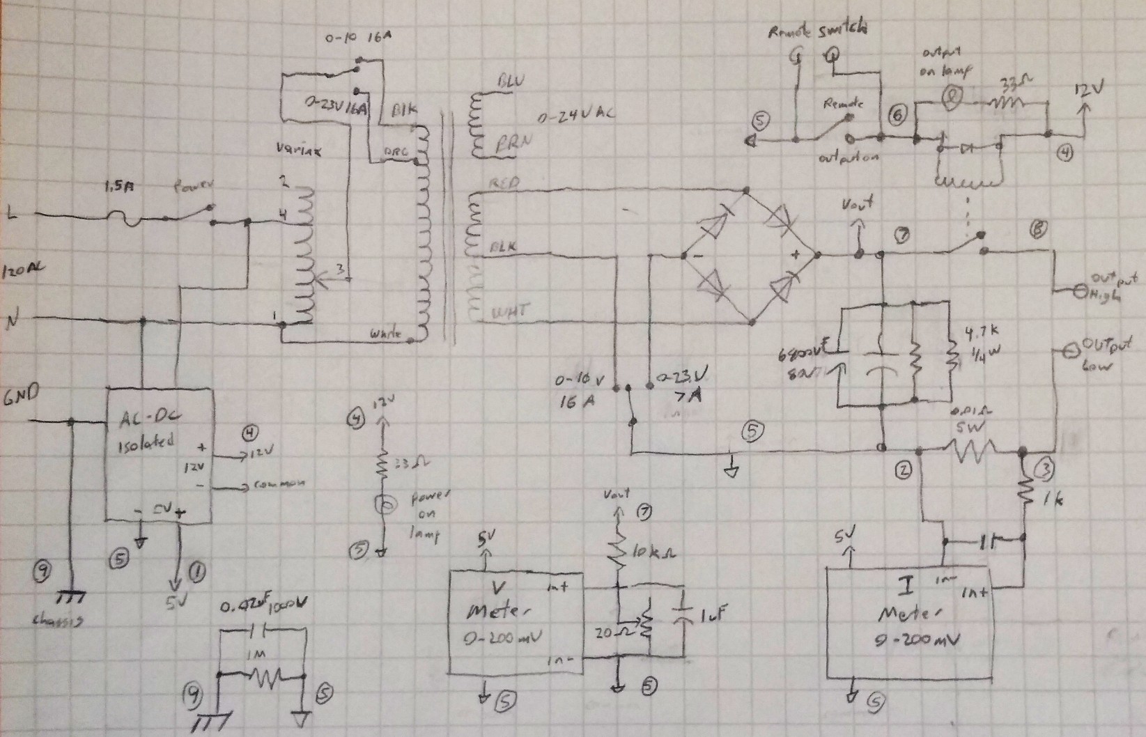
Things to note:
- I added a switch to select if the output supports higher voltage or higher current. This changes the rectifier circuit.
- Because the switch I have for that which supports this current is DPDT, I'm using the other pole to change the transformer input winding as well. The transformer has 2 taps on the high side for adjusting the voltage. This bumps the ratio up(and output voltage down) when in the high current mode, allowing a bit more current.
- For the output caps, I found and am using 2 @ 6800uF 80V caps in parallel. These have two 4.7kohm resistors to bleed the voltage when powered off.
- The circled numbers reflect connection points on the circuit board terminals.
- The output/low voltage side is floating from ground. To avoid building up a static voltage on it, the output common is tied to the chassis by a 1Mohm resistor and a 0,022uF cap.
- Because I didn't have any leaded 1% 10k and 10 ohm resistors for the voltage meter divider, I used a 10k and a 20ohm multi-turn pot instead of the 10 ohm. This will let me dial in the divide by 1000 needed to scale V to mV for the meter.
Discussions
Become a Hackaday.io Member
Create an account to leave a comment. Already have an account? Log In.