Quinn
Quinn-
Power supply part 4
02/19/2021 at 22:51 • 0 commentsAfter considering the options, I've been leaning recently towards just using stock of things I already have, so am going to further explore the diy solution with a variac and large transformer.
While the transformer supplies 17.1VAC, wiring the variac for it to give 110% of the input on the output, this provides 18.8V output. Further, if I rectify if and smooth with a large cap, the no load voltage would be 26.6V. Drawing current from that will make the output more pulsing with that peak, and the minimum depending on how large of a capacitor and how much current is drawn. Needing the higher voltages only happens with the thinner gauge wires, which require less current. This may allow a moderate size capacitor to ensure an average higher voltage when needed, and when running at higher currents and lower voltage the output won't be completely DC, but that isn't important for a heater resistive load. Estimate is that I need 10000uF to keep the droop down to 1.7v when drawing 2a, though this is worth testing to confirm.
I will need to take care about filtering so that the meter can measure the average voltage and current. A simple R-C should suffice. The meter has a 909kohm input impedance, so there is plenty of room for the RC. The time constant just needs to be a bunch longer than the 1/120 sec period pulses.
-
Power supply options: DC regulated
02/19/2021 at 22:38 • 0 commentsTwo other supply options stand out. Using a lot cost switch mode bench supply module, or using lipo batteries.
Bench supply module
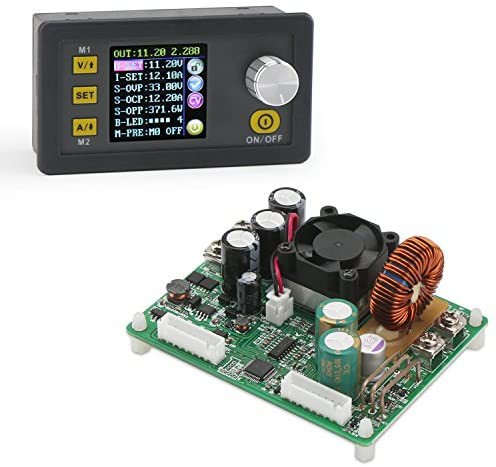
A range of bench supply modules are on the market which could be used. They have an LCD and interface for setting voltage and current. Having a constant current mode is the biggest thing going for it as one doesn't need to worry about the voltage when changing wire lengths. Just set the current for that gauge/resistance of wire, and it'll adjust voltage for whatever length of wire is used.
This one should be plenty capable, able to supply 15A and up to 50V.
![]()
The big catch with these modules is that not only do you need the module, you need an AC-DC supply to power them. Add on a 300w+ 48VDC supply, and that $50 isn't so low, and it is getting pretty sizable. One could probably get away with an unrelated supply from a transformer, rectifier and cap, though I don't think I have an appropriate transformer. I believe I do have a AC-DC supply that could work, but this is getting quite large and is a bit more spendy on top of still needing to do all the mechanics.
Li-po supply
One of the advantage of hobby li-po batteries is they can supply a lot of current for relatively low cost. A brushed motor ESC and a servo tester to drive it ensure it can even regulate the power. This makes for a portable setup, even capable of putting it all on the bow itself so there is no lead to it.
The downsides are that it requires charging in advance, the power will dip as the battery drains requiring adjustments between cuts, and it would still need a voltage/current display.
I do have suitable batteries, though I don't have a brushed ESC or servo tester, so I'd need to purchase those.
-
Power supply options: unregulated diy
02/15/2021 at 19:46 • 0 commentsI do have sufficient parts on hand to build a suitable supply, though it's likely to be bigger and heavier than I'd like. This would be unregulated, transformer based.
Main transformer
I have a number of higher current output ones.
A 6.3v, 20A, which isn't terribly large. This won't work great for the bow however with such a low voltage. It would be great for a rigid wire cutter though.
From a large UPS, I have a transformer that I expected to be 120v to 24v, probably 50A. The backup used a 24v battery, though I don't remember if the drive was a full bridge or single bridge. I ended up testing it. There is a 120v coil, and a lower current secondary 14v coil. The main output is 14v however. Given the UPS power, this must be 70A. It's huge and heavy, overpowered and lower voltage than desired.
From a second large UPS, I tested it's transformer to be 13.6 or 15.7V output depending on which 120 input tap is used. I don't have a way to know the output current, but based on the wire, it's probably 90+A. Given that this is a 24V battery system, I'm again surprised the low voltage side is this low, but I guess it must work better for these high power systems.
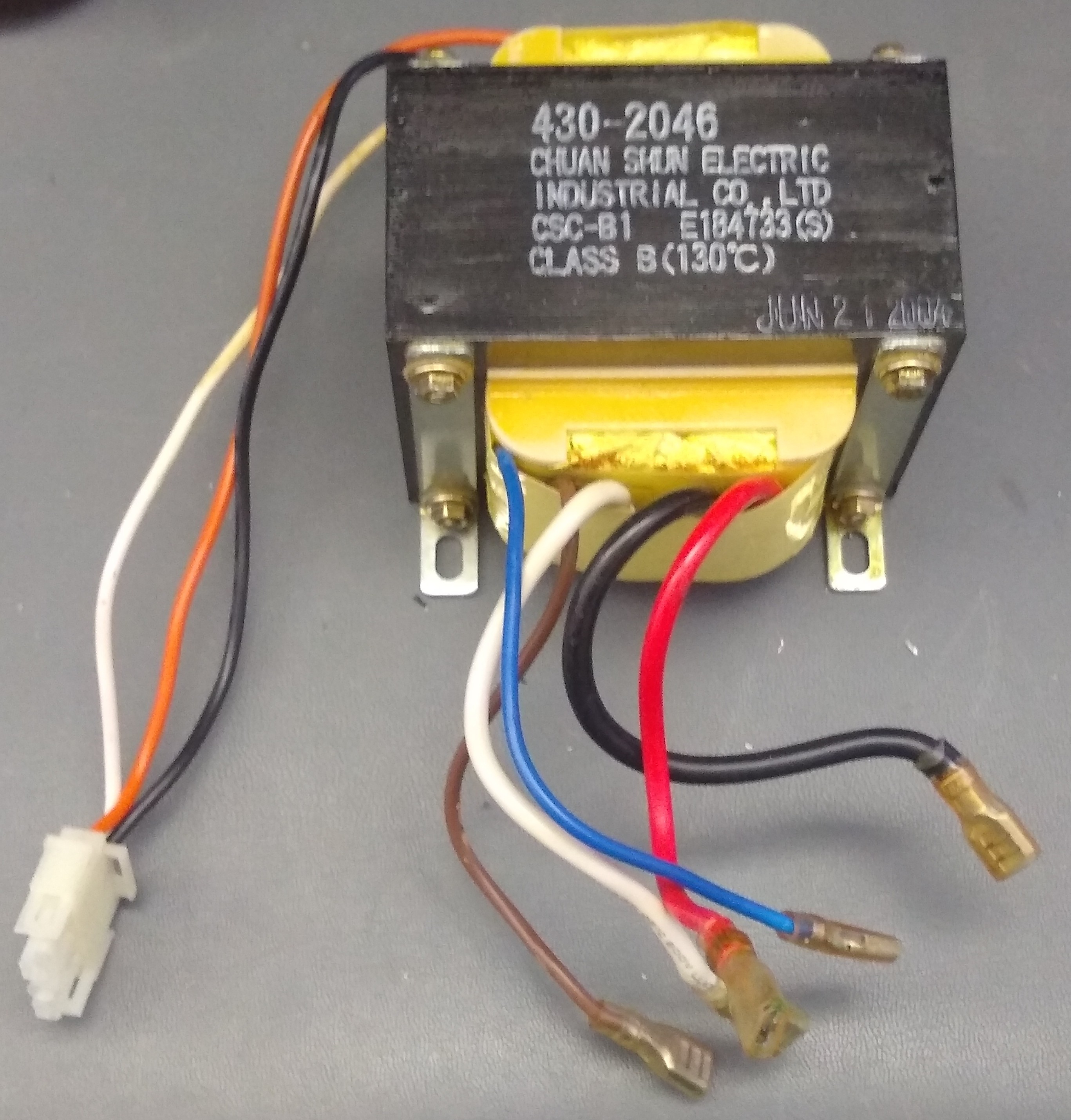
From a smaller UPS, I have a transformer I tested to be 120 to 17.5v, center tapped, probably 17A. I know this circuit switched the 12v back and forth between each side of the center tap in order to get sufficient voltage from a 12v battery.
Another one from a UPS also has 17.5vac output, center tapped, likely 23A. There is also a smaller 24V output coil. It also has a second tap on the higher voltage end, likely used to get a higher output boost when on battery.
![]()
Variac
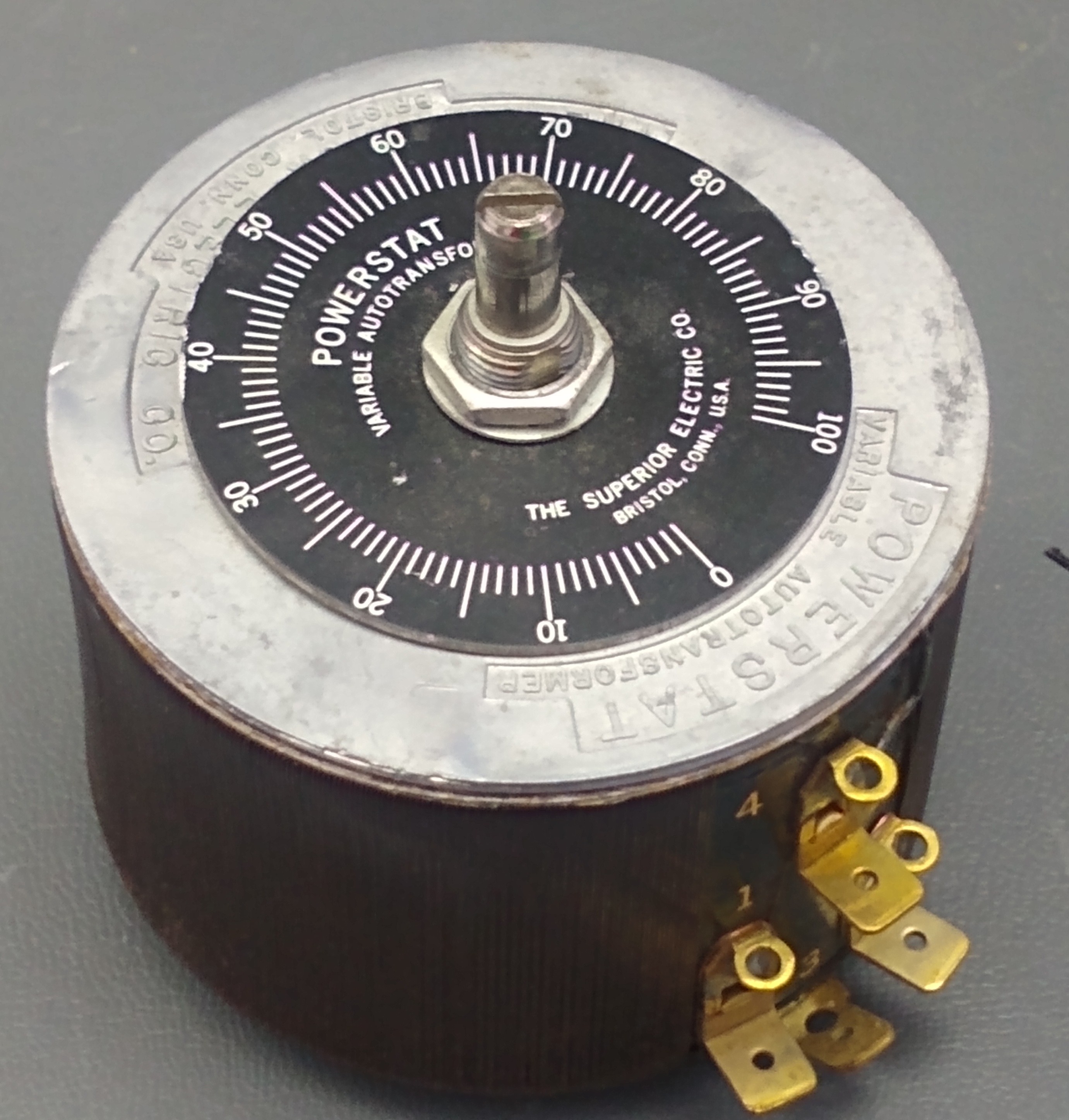
To adjust the output voltage, I have a number of variable transformers that could be used. These could feed the input of the transformer for smooth voltage adjustment. All of these can be wired to output 0-100% or 0-110% of the input.
I have a bunch of 1.75A variacs. These are reasonable size, and would handle up to 210W at the maximum transformer output voltage. Equivalently, with that smaller UPS transformer, output up to 12A, which is sufficient for the direct needs. With the larger transformer, it would be lower current.
![]()
I have a pair of 3A variacs, a little bigger, and would handle a bit more power.
Past that, I have a couple stand-alone variacs about 7 or 8 amps.
And I have a pair of 20A variacs, which are huge and heavy.
DC
I think regardless, I'd like to rectify the transformer output and put some caps on it to smooth it out. I should have a handful of 15A bridges, but also some much higher power diodes if I wanted to go higher.
Metering
To help be more consistent with cutting, I'd like voltage and current metering on the supply. At first I dug through my analog meters, but I didn't have a good matched pair.
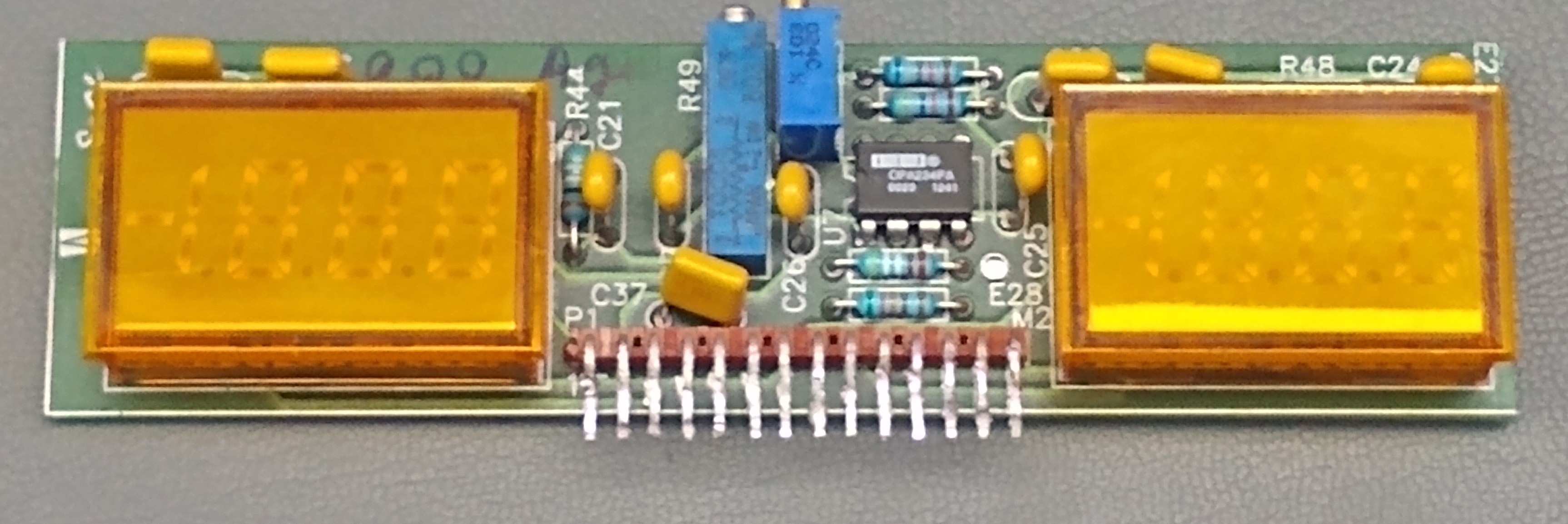
Instead I found a set of these modules I unsoldered from some power product. Thankfully I worked out the pinout and wrote a note so it was pretty easy to get going.
![]()
These use 0-200mV voltmeter modules, Datel/Murata DMS-20PC-0-YS. The volt side directly connects to the module input pins, so I simply need to scale with a resistive divider.
The current side has a OPA234PA op-amp to drive the meter input. Input pins feed the op-amp. I didn't work out the values in the op-amp feedback, so I'm not certain the gain. It was originally set to measure over a 600A/50mV shunt, so 83uohm. Based on the original application, this implies it's configured for a 1.2x gain. There are a couple multi-turn pots, one in the feedback loop which can adjust gain, and one as a zero adjust. The op-amp I assume is in this circuit in order to scale based on the odd value current shunt.
I was able to find a 0.01ohm 5W resistor in stock I can use as my shunt, which can directly feed the meter (without the op-amp). Given that the existing circuit gain could not reach a useful value, I will just disconnect the op-amp output from the meter and feed it directly from my shunt. This shunt will work for 0-19.99A on the meter. The meter does support negative, but I don't think it's useful here. If I wanted to use a different shunt for higher current, I could adjust the op-amp feedback. Without using the op-amp, the board only needs 5v. The op-amp requires +/-12V.
Overall
I think this leaves 1 option I'm considering for building the supply so far.
One of the 1.75A variacs feeding one of the smaller UPS transformers. This would result in 0 to 17.5 V output, 12A max. While the 12A is fine, 17.5 V will prevent long higher gauge wires. Using the 110% wiring for the variac, would result in 19.25V, which is a bit better.
I could use the 3A variac to increase the current a bit, but that isn't really important in this situation.
-
Power supply part 1
02/15/2021 at 15:59 • 0 commentsFor a power supply, I'd considered several options.
A bench supply can be directly used, with advantage of using constant current mode. While I have several, they are all larger and set up at my bench, not convenient to move around. As cutting needs to be done in a well ventilated area, moving one of these to the garage every time would be a nuisance.
There are quite a few lower cost switch mode power supplies which could be used. I would prefer to use things from my stock however. This model for $50 seems like good capability, though I'd still need to dig up a ac-dc supply with sufficient voltage and current and a case.
A battery powered solution would be to use a moderate or larger size hobby lipo battery(3 or more cell, 2000+mah). A brushed motor speed controller can be used to regulate the power, and a servo tester used to control the speed controller.
I could also make my own, which I've also decided to explore, given all the stock of parts I have.
Needs
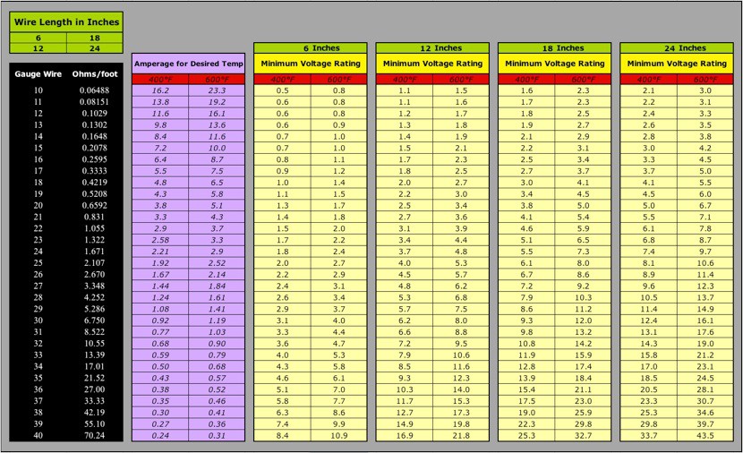
This table from http://hotwirefoamcutterinfo.com/Introduction.html is super helpful for estimating the current and voltage needed for various wires. Unfortunately it doesn't go out to the wire length I need for the bow, but having the resistance table and needed currents are the key, and can easily sort out the voltage for a given wire length.
![]()
Hot wire foam cutter
A power supply, bow and table for cutting foam with a hot wire