A: LOCALIZATION AND MAPPING
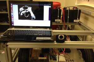
The camera was placed at the roof. Firstly an image was taken without the robots and obstacles. This image served as the reference to locate obstacles.
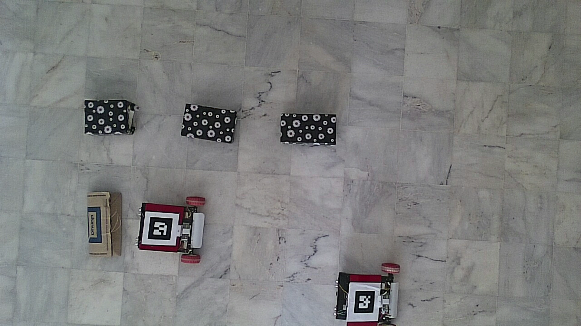
For localization of the robots a tag was placed on both the vehicles. These tags are used to extract the position and orientation of the vehicle from the image.
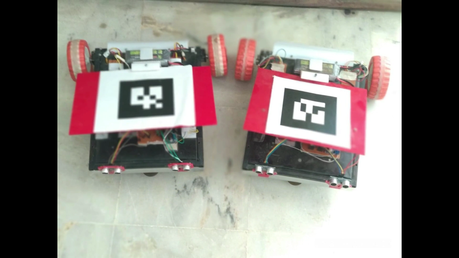
Since the tags were black and white, therefore it allowed us to eliminate the complexities of color image processing. For mapping out obstacles the image was compared to a reference image and the resultant image was divided into grids and averaged over a single grid.
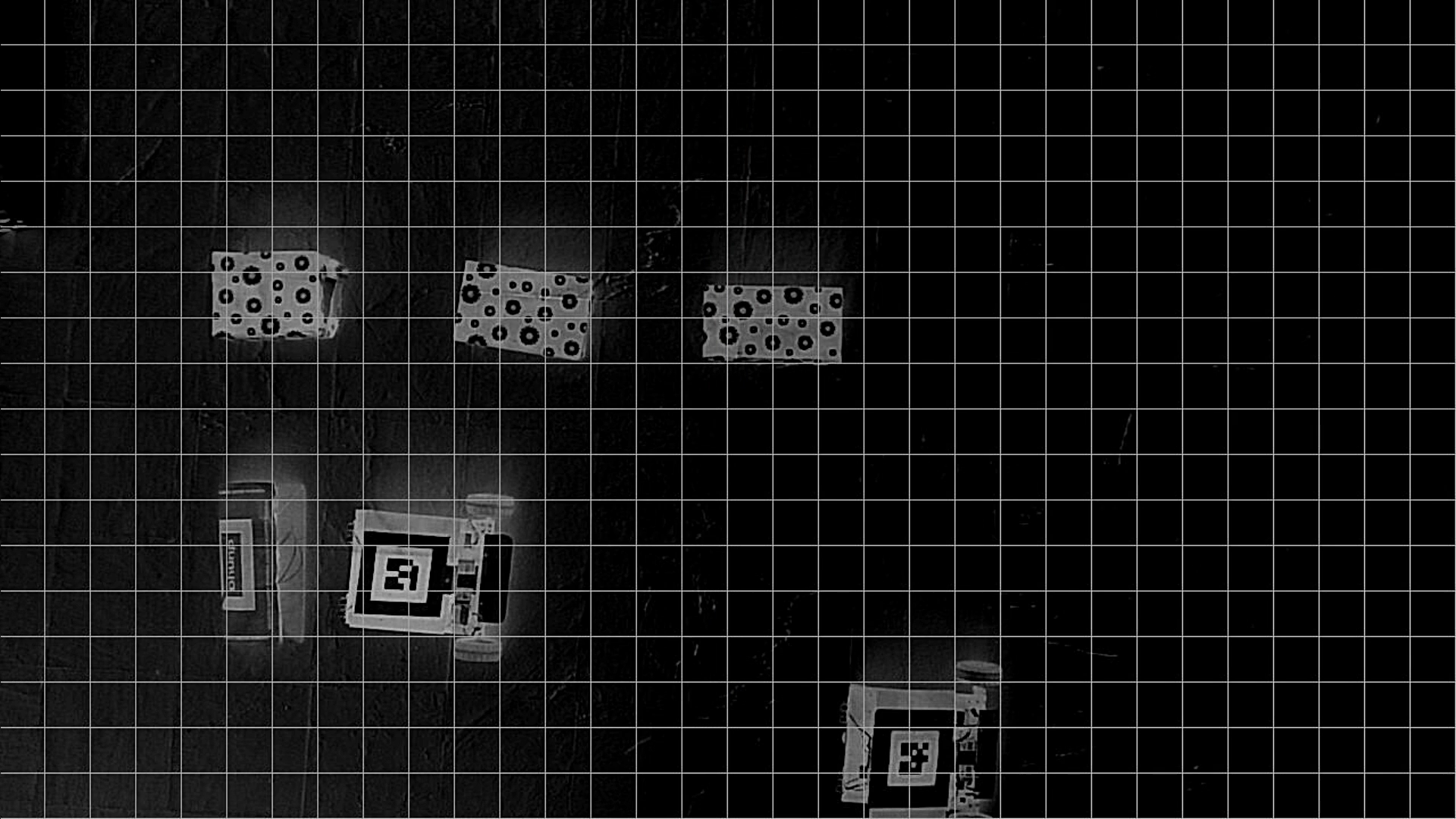
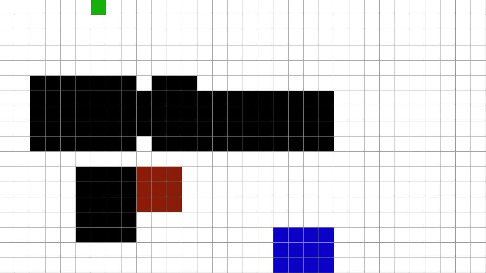
After averaging a grayscale threshold was set and image was digitized to 2 colors only. Since the vehicle consisted of several grids in the image therefore the grids adjacent to obstacles were also considered as obstacles. Finally the coordinates of vehicles were masked into the resultant image to produce a final map. This map included the position of both the robots and how obstacles were placed around the robots
B. PATH PLANNING
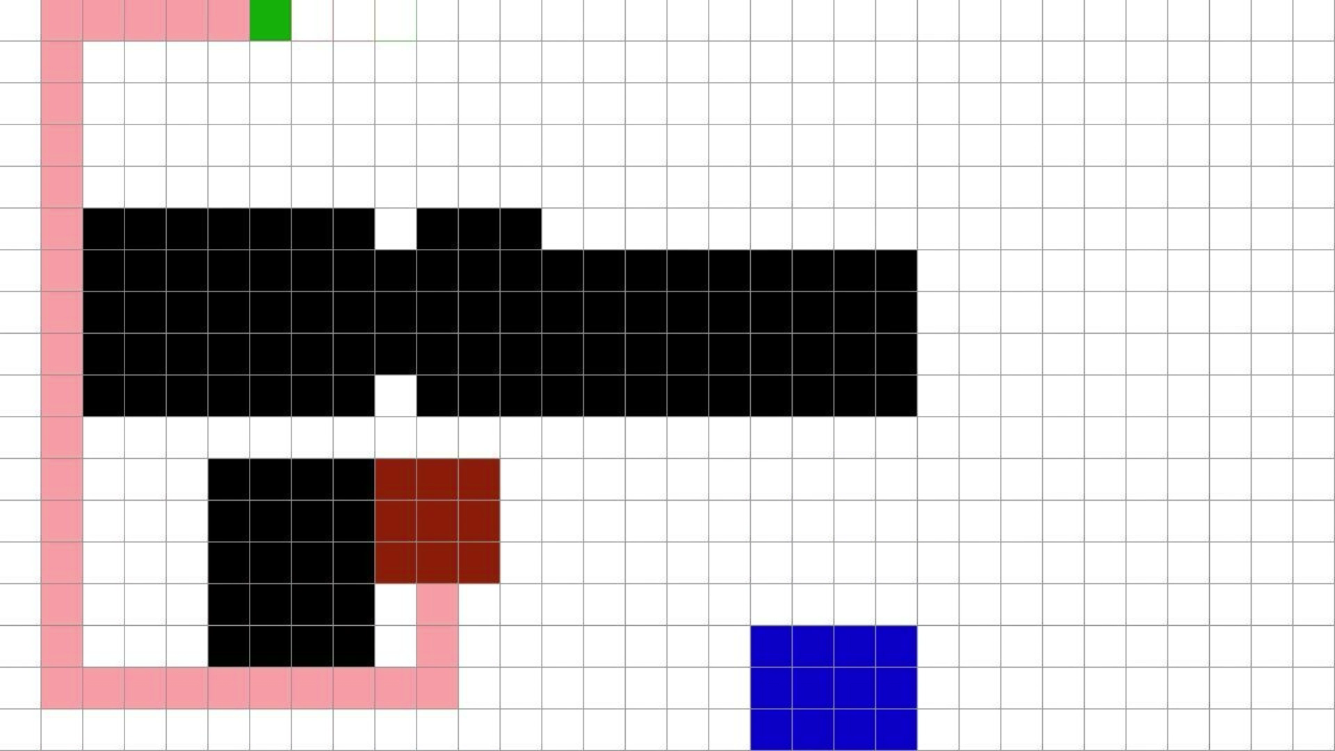
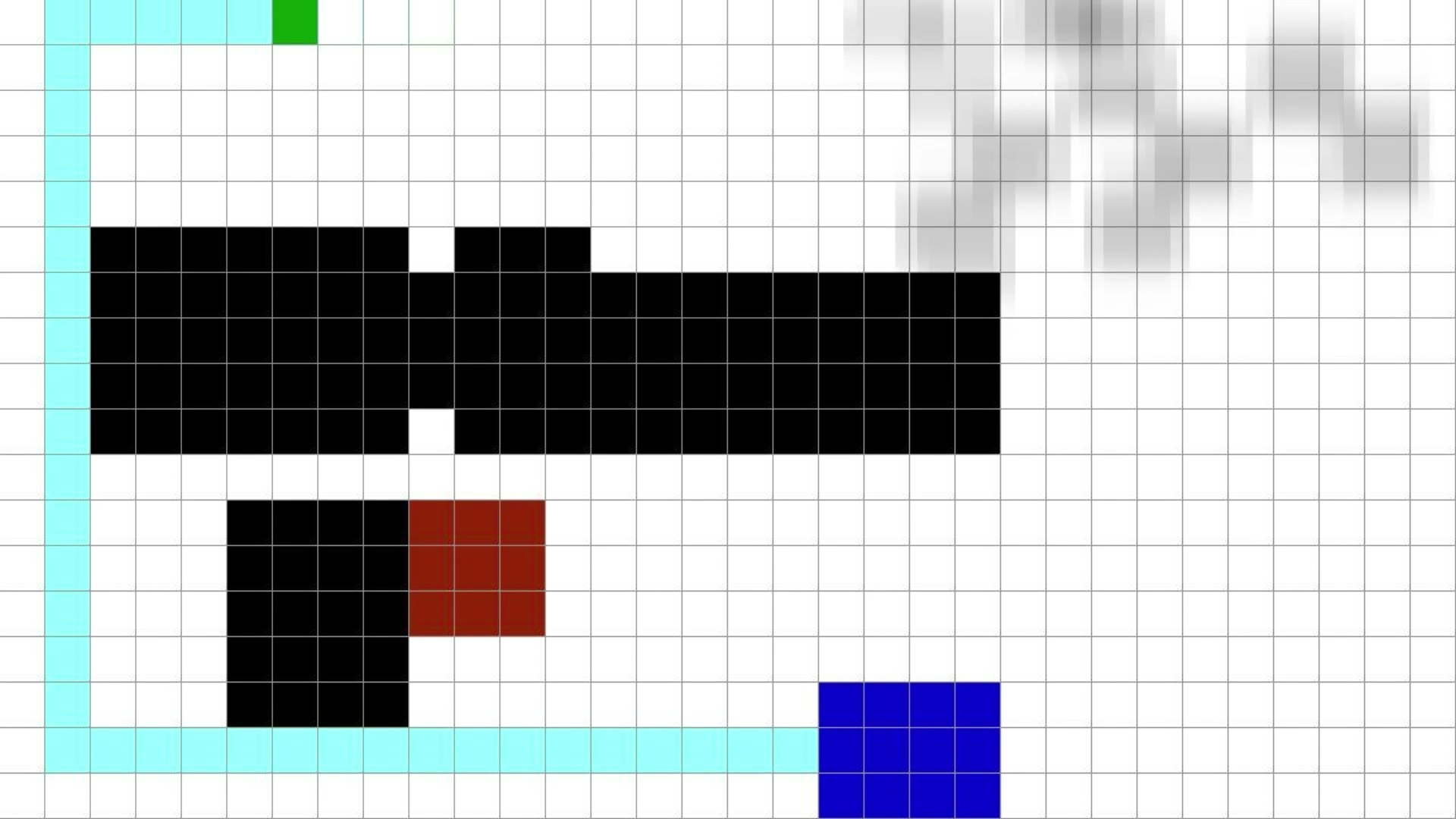
Path planning for both the vehicles was done by using A* algorithm. For each node 4 of its adjacent
nodes were considered as its neighbors so robots can only take 90 degrees turns. For the optimization of algorithm priority queue was used as the data structure for maintaining the adjacency list of the expanded nodes. As the A* algorithm tends to go for the node which minimizes its cost function, therefore it is really important to select your heuristic function to optimize the Algorithm. Manhattan distance was used as the heuristic function because the robot was allowed to
move in four directions only. The shorter of the two path is conveyed to its corresponding robot. The path is split in such a way so the vehicle can move grid by grid.
C. PATH TRACKING
The real task was to improve the accuracy of path tracking with a considerable increment in the speed of vehicle for that purpose the Encoder DC motors were used for linear motion and to make sure that the vehicle is moving straight MPU6050 was used. When the vehicle started moving the initial value of the Gyro sensor was saved as a reference and using that value the deviation in the angle of vehicle was monitored. The speed of both the motors were varied corresponding to the deviations in the angle so as to keep the robot moving in a straight line. For each 90 degrees turn
The Gyro sensor tried to turn 90 degrees but due to the inaccuracy of Gyro it was rarely able to complete its 90 degrees turn. Therefore a discrete feedback from camera was taken after every attempt by the robot to turn a full 90 degrees and a control signal was generated proportional to the error which compensates for the inaccuracy of gyro sensor. During the path tracking if
any dynamic obstacle was introduced into the system and it intercepted the path of robot then the robot stops and the process was repeated to plan a new path. The dynamic obstacle was identified by the ultrasonic sensor placed in front of robot.

 tommytwoeyes
 Jack Qiao
 SerialSensor
 Tom Quartararo
Hi, are you planning to share implementation details necessary for others to build their own? Mechanical construction of vehicles, their electrical schematics, OpenCV source code, etc.