Close
0%
0%

RP2040 : PIO - case study

This is a small research on how to use the Raspberry Pi Pico's PIO module.

Similar projects worth following
We all know how to bit-bang, wait and more bit-bang when we have to control something that is not supported in a hardware manner. This RP2040's PIO module is going to change all that.

Required to read the PIO part in the Pico SDK Manual and RP2040 Datasheet first to get an idea how it works!

If you are using Windows 10 and FT2232H and needed to deploy the SDK - refer to this guide first: https://hackaday.io/project/177166-rp2040-quick-setup-guide-for-win10-and-ft2232h

Afterwards, you can deploy VSCode on it: https://hackaday.io/project/177811-rp2040-deploy-vscode-in-win10-and-ft2232h

Else, if you are using Linux and Raspberry Pi, the environment and SDK are already fully deployed once the SDK is installed.
  • 1 × Raspberry Pi Pico
  • 1 × ST7920 display (optional)
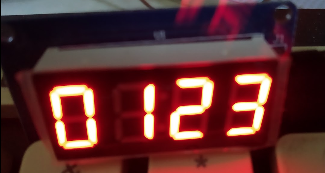
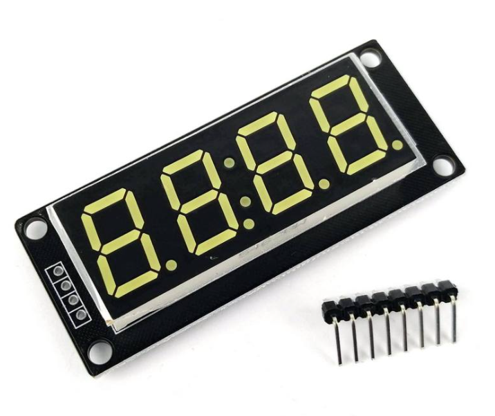
  • 1 × TM1636 display (optional)

  • TM1637 - Must send command + command and command + data!

    YH-workshop02/21/2021 at 08:12 0 comments

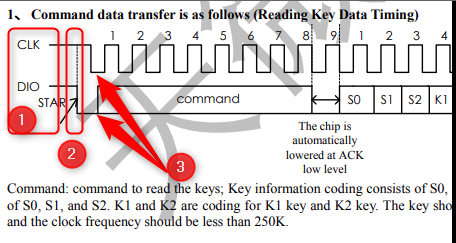
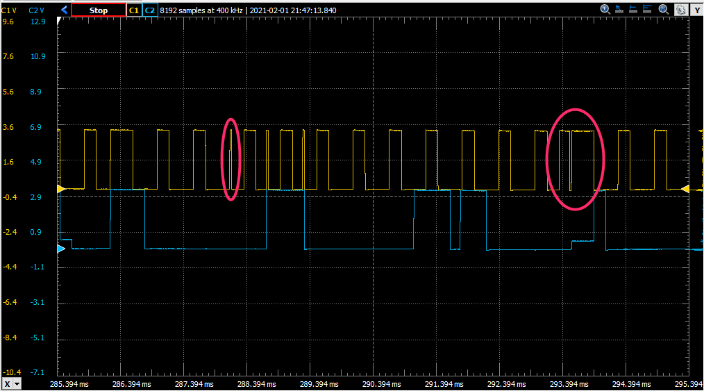
    As said earlier in the log, we can't "call" since it doesn't have one. And trying to distinguish "sending only command" and "sending command + data" could be a tedious work. What is tried is to separate these two using two separate state machines, but it ends up breaking the signal (the circled one showing the spurious pulses in the CLK line):

    To provide a temporary fix, it has to push both command + command and command + data pairs to the TM1637 using the PIO.

    .wrap_target
    
    pull block
    set y, 1
    
    _twoCmds:
    
    _startCond:
       set x, 7
       set pins, 1 side 1 [7]
       set pins, 0
       set pins, 0 side 0
    
    _bitShiftLoop:
       out pins, 1 side 0 
       nop side 1
       jmp x-- _bitShiftLoop side 0
    
    _ackCond:
       set pins, 0 side 0
       nop side 1
       nop side 0 [1]
    
    _stopCond:
       set pins, 0 side 1
       set pins, 1 side 1
    
    jmp y-- _twoCmds 
    
    _startCond_sendDigit:
       
       set y, 1
       set pins, 1 side 1 [7]
       set pins, 0
       set pins, 0 side 0
    
    _sendCmdAndData:
       set x, 7
    _bitShiftLoop_sendDigit:
       out pins, 1 side 0 
       nop side 1
       jmp x-- _bitShiftLoop_sendDigit side 0   
    
    _ackCond_sendDigit:
       set pins, 0 side 0
       nop side 1
       nop side 0 [1]
    
       jmp y-- _sendCmdAndData
    
    _stopCond_sendDigit:
       set pins, 0 side 1
       set pins, 1 side 1

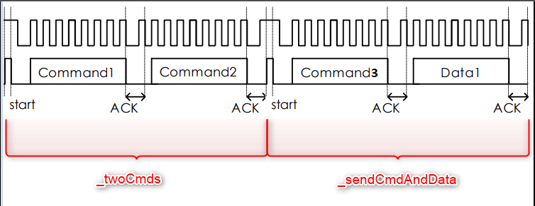
     _twoCmds: referred to the two 8-bit of commands (must be command, not data!) being sent.

    _startCond_sendDigit: referred to the next 8-bit of command and 8-bit of data being sent.


    This arrangement looks tedious since we can't send one command alone, or one command, then continuous data or other way we can imagine. On this restriction, it must be only two commands, then another one command with one data.

    To go around this, every time we set a digit on the TM1637 here, we had to:

    1.) set the brightness (0x8a -> Display On, 4/16 brightness) [command1]

    2.) set the mode (0x44 -> Fixed address) [command2]

    3.) set which digit (c0 -> first digit) [command3]

    4.) Finally, set the segments (0xff -> all segments on here!) [data1]

    Example:

    pio_sm_put_blocking(pio0, 0, 0xffc0448a);
    

    Luckily, we can send a maximum of 32-bits into the PIO module, and sending these two pairs actually total to 32-bits. What a coincidence!


    So here's the review on the PIO module to drive a TM1637. Due to the modified two-wire interface, distinguishing between send only command, or sending command with accompanying data might be a tedious work, and might not fit into the 32-instruction space on the PIO module. To simplify it, we only send two commands and then one command coupled with one data. Unfortunately, we can't read the data from TM1637 and only write digits to it. This tradeoff is minor because there are no keypads on this module, and we can live with that. :)

    Here's the git for this project: https://github.com/nyh-workshop/rpi-pico-tm1637-pio

  • TM1637 - Introduction

    YH-workshop02/21/2021 at 03:58 0 comments

    This little display module is very common and being sold everywhere. Thousands of Arduino projects are possibly using these too.


    The very strange part is, despite this is using the 2-wire interface, it isn't any I2C! Connecting this and expecting it to work like I2C will not get you anywhere!

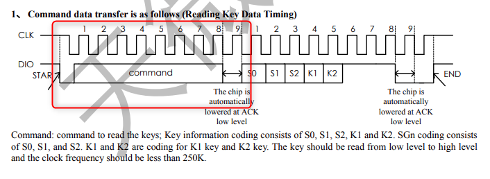
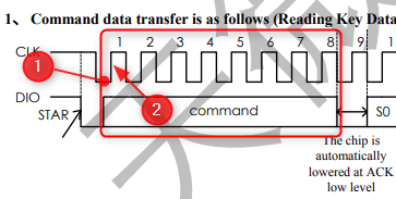
    Why? It's simple - this thing is a modified I2C interface. Its I2C address isn't there:

    Obviously, we got to bit-bang it. That's the first thing to do.


    But since the RP2040 has a PIO module, why not we spare ourselves from doing the casual bit-bang?

    With that PIO, we try to imitate the behaviour of how it sends the stuff bit by bit (no pun intended!).


    Start Condition:

    _startCond:
       set x, 7               ; (4)       
       set pins, 1 side 1 [7] ; (1)
       set pins, 0            ; (2)
       set pins, 0 side 0     ; (3)

    In this code the "pins" is set to be referring to the "DIO", while the "side" is referring to the "CLK".

    These PIO instructions are known to work in parallel manner, where you can change a pin state and another at the same time too. If you look at (1), this loosely translates to: "set the DIO 1 and at the same time set the CLK 1 and delay for 8 PIO cycles".

    At (4) this "set x,7" just means set the x register to 7. This will be used in the following operation.

    Shift the Bits:

    _bitShiftLoop:
       out pins, 1 side 0            ; (1)
       nop side 1                    ; (2)
       jmp x-- _bitShiftLoop side 0  ; (3)

    That "out" instruction just means shift out a bit. Here, at (1) it translates to "shift out 1 bit from the DIO, at the same time 0 on the CLK line".  Then on (2), just "nop and 1 on the CLK line".

    About that x register earlier? Since shifting is being done for 8 times, so the "jmp x-- _bitShiftLoop side 0" just means to "jump to _bitShiftLoop, if x is not yet zero, else decrement, and finally at the same time pull down the CLK pin to 0".

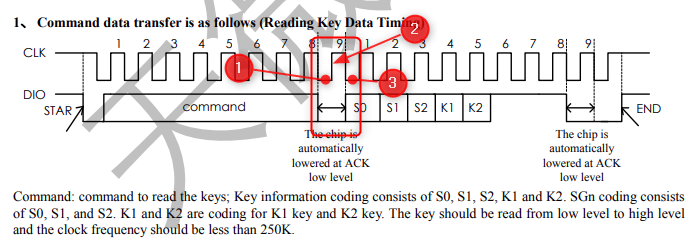
    Acknowledge bit:

    _ackCond:
       set pins, 0 side 0  ; (1)
       nop side 1          ; (2)
       nop side 0 [1]      ; (3)

    Again, this PIO code mimics how to perform that ACK bit.


    Stop bit:

    _stopCond:
       set pins, 0 side 1
       set pins, 1 side 1

    To end the transmission successfully.

    This is how the PIO will mimic the TM1637 protocol. Note that we are sending the command only, not its data. We need to start, send the command, then the data, and then end. However, this 9 instructions in PIO doesn't help at to "recycle" some parts of the code (due to the lack of "call" operation) , or to further distinguish if it is a data or a command that have to be sent.

  • Introduction

    YH-workshop02/21/2021 at 03:16 0 comments

    Like explained in the front page, we all know how to bit-bang, wait and more bit-bang when we have to control something that is not supported in a hardware manner. 

    Most of the microcontrollers in the market will have a hardware SPI, I2C and other protocols. This allows users to just simply send and receive the data without a lot of firmware/software intervention. However, some hardware contains custom protocols that demand bit-banging if the microcontroller system doesn't have it. It would be fine if this hardware isn't high speed. What if it needs that high speed? Or what if you need to do a lot of things in between and then also have to bit-bang? When it reaches to this situation, you know it is not going to be pleasant anymore. 


    The most fun and strange part about this RP2040 is, this PIO module is going to save the day.

    As a summary, from its datasheet:

    The programmable input/output block (PIO) is a versatile hardware interface.
    
    It can support a variety of IO standards,
    including:
    • 8080 and 6800 parallel bus
    • I2C
    • 3-pin I2S
    • SDIO
    • SPI, DSPI, QSPI
    • UART
    • DPI or VGA (via resistor DAC

     You can program this thing to do whatever protocol you wanted, with these precisely timed and deterministic instructions.

    In this article, explaining how we can use the PIO module to drive some simple LED/LCD displays.

View all 3 project logs

Enjoy this project?

Share

Discussions

Similar Projects

Does this project spark your interest?

Become a member to follow this project and never miss any updates