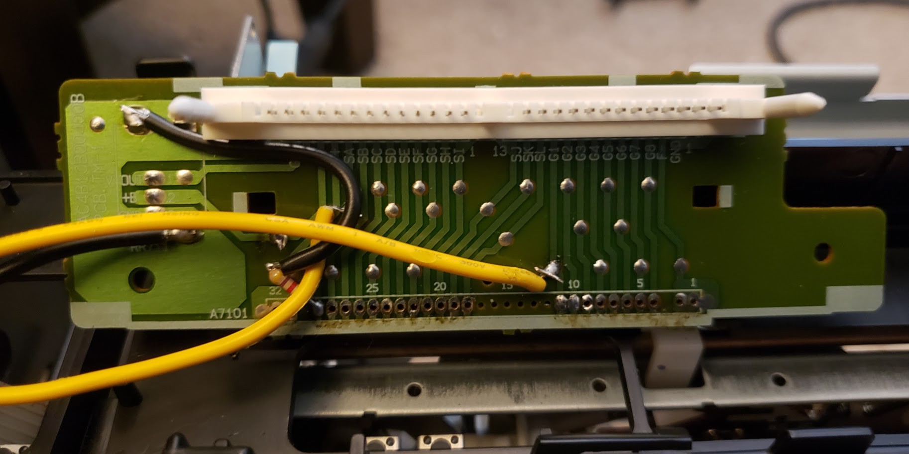
I was able to get the service manual PDF to the VHR-9413A from a nice chap in the Netherlands. I also found the JAPANESE datasheet of the LC86P6648 which I've concluded is very similar to the LC866636. The differences I've concluded are with memory configurations. With the service manual I felt confident to remove -23v from pin 48, with is the "VP" input. VP is listed as the VFD's negative power rail voltage.
I connected VP to GND. I pulled SA and G1 to GND, and was able to get nice 5v sine waves of these signals.
There are 20 lines in total. To get them to 3.3v, I'm going to cut all 20 signals, add inline resistors, and pull them down after to create voltage dividers.

 Ted
Ted
Discussions
Become a Hackaday.io Member
Create an account to leave a comment. Already have an account? Log In.