WJCarpenter
-
Turbines to speed!
03/14/2021 at 18:24 • 0 commentsI wanted to find out how long the M5StickC can run on its battery under various conditions. That would give me some idea of the usability of RemotMCS as a ... remote. How to measure?
The simplest thing I thought of was just having it "Serial.println()" something every once in a while. The Arduino IDE serial console would timestamp them so I could know when the last one came in. The problem with that is that the M5StickC charges its battery and runs off USB power when it's plugged in. I can predict in advance that the answer would be something like infinity.
What about doing the equivalent over Bluetooth? Paired to a PC, I could just leave an editor window open and have the M5StickC "type" some time information periodically. RemuterMCS doesn't know time of day, but it does know the amount of time since the ESP32 startup. This scheme would probably work, but it has a couple of drawbacks. My primary concern is that I don't know how much the Bluetooth interaction would affect power consumption, so I wasn't sure I could get a baseline of "while doing nothing". Second, I know from past experience that I have a good shot at goofing up the recording now and then. If the battery life is 4-5 hours, then it's an overnight wasted on a bungled test. Finally, I have a preference for something that is simpler for someone else to replicate so they could perform the measurements on their own specific M5StickC devices. In fact, I have a few of these and might want to measure them all to see if there is variation in available power.
The solution that I adopted was to periodically store timing information on the M5StickC itself. On start-up, I read it back out and report it. I report it with "Serial.println()" and, in the early stages of the code, on the device display. I don't know if I'll show it on the device display when the UI is complete.
With true Arduinos (without SD cards or other storage devices), that's done using a mechanism called PROGMEM. On an ESP32, PROGMEM is a no-op. Instead, the ESP32 Arduino libraries provide a mechanism called "Preferences", which is a straightforward key-value store. It operates on some part of the device's flash memory. I didn't chase down the details of the flash partition scheme and where the preferences values live; I just tried it and it worked as advertised.
Now, of course, I don't know how much power it takes for the ESP32 to write those values to flash via the Preferences API. I'm just hoping it's not much. I write the time since startup every 10 minutes. A 10 minute (rounded down) granularity for battery life should be fine unless I get into some really detailed fine-tuning, which I don't expect to do. It also means I have 10 minutes of false starts and shenanigans before the value gets overwritten after a device restart.
The mechanism is enabled with a single define. I won't quote all of the code here, but this is the gist (snapshot in time; check the git repo in case it changes, which it surely will).
#define LONGEVITY 1

#if LONGEVITY
#include <Preferences.h>
#endif

#if LONGEVITY
const char *key_naptime = "naptime";
const char *key_longevity = "longevity";
unsigned long lastSaveMillis = 0;
unsigned long saveEveryMillis = 600000;
unsigned long storedLongevity = 0;
unsigned long storedNaptime = 0;
Preferences preferences;
#endif

void setup() {
// ...
#if LONGEVITY
  preferences.begin("RemuterMCS");
  storedLongevity = preferences.getULong64(key_longevity);
  storedNaptime = preferences.getULong64(key_naptime);
  preferences.end();
  Serial.printf("Stored longevity = %ld, naptime micros = %ld\n", storedLongevity, storedNaptime);
#endif
// ...

void loop() {
// ...
#if LONGEVITY
  unsigned int now = millis();
  if ((now - lastSaveMillis) > saveEveryMillis) {
    lastSaveMillis = now;
    preferences.begin("RemuterMCS");
    preferences.putULong64(key_longevity, now);
    preferences.putULong64(key_naptime, napDurationMillis);
    preferences.end();
  }
#endif
// ...
}
The "naptime" referenced in the code is because I anticipate doing some kind of low power sleep in most iterations of the loop to conserve power. But that's a topic of its own.
-
Clicking the buttons
03/06/2021 at 20:22 • 0 commentsSince the RemuterMCS device user interface is a series of dolphin-like clicks and pops, I wanted to outsource the button handling as much as reasonable. I didn't feel like writing fiddly timing code myself. There are many button-handling libraries for the Arduino IDE ecosystem. I spent a little time looking at a few of those, and I have settled on using AceButton by Brian Parks.
The main reasons that I like that particular library:
- It provides the button features I want (single click, double click, multiple buttons) and some others that I might find a use for later.
- The quality of the documentation and sample code is great. Also, the author's explanation of why and how they wrote the library is consistent with how I think about things.
- It uses an event callback scheme for button activity. Novices may find that a bit confounding, but it's second nature to me and will greatly simplify the code I write using the library.
- The library API looks clean and sensible.
- The most recent versions of it are included in the Arduino IDE library manager, which is convenient.
I did some quick experiments with this library, tweaking the sample code, to make sure it works as advertised. I didn't doubt that it would, once I had read through the extensive documentation. Here is a sketch, KeysAndClicks, that reacts to single and double clicks by printing the targeted reaction on the serial console (which it expects to be configured for 115,200 speed).
/**
 * Reacts to single and double clicks, but the reaction just prints
 * what should happen.
 */

#include <AceButton.h>
#include <M5StickC.h>

using namespace ace_button;

const int LED_PIN = M5_LED;
const int LED_OFF = HIGH;
const int LED_ON  = LOW;

// The pin number attached to the button.
#define ACTION_BUTTON_PIN M5_BUTTON_HOME
#define MODE_BUTTON_PIN   M5_BUTTON_RST

AceButton actionButton(ACTION_BUTTON_PIN, HIGH, 1);
AceButton modeButton(MODE_BUTTON_PIN, HIGH, 2);
AceButton *buttons[] = {&actionButton, &modeButton};
const uint8_t NUMBER_OF_BUTTONS = sizeof(buttons) / sizeof(buttons[0]);

void setup() {
  Serial.begin(115200);
  Serial.println("Starting");

  pinMode(LED_PIN, OUTPUT);
  turnLedOff();

  pinMode(ACTION_BUTTON_PIN, INPUT_PULLUP);
  pinMode(MODE_BUTTON_PIN,   INPUT_PULLUP);

  // using method 3, ClickVersusDoubleClickUsingBoth, to distinguish clicks
  ButtonConfig* actionButtonConfig = actionButton.getButtonConfig();
  actionButtonConfig->setEventHandler(handleButtonEvent);
  actionButtonConfig->setFeature(ButtonConfig::kFeatureDoubleClick);
  actionButtonConfig->setFeature(ButtonConfig::kFeatureSuppressClickBeforeDoubleClick);
  actionButtonConfig->setFeature(ButtonConfig::kFeatureSuppressAfterClick);
  actionButtonConfig->setFeature(ButtonConfig::kFeatureSuppressAfterDoubleClick);

  ButtonConfig* modeButtonConfig = modeButton.getButtonConfig();
  modeButtonConfig->setEventHandler(handleButtonEvent);
  modeButtonConfig->setFeature(ButtonConfig::kFeatureDoubleClick);
  modeButtonConfig->setFeature(ButtonConfig::kFeatureSuppressClickBeforeDoubleClick);
  modeButtonConfig->setFeature(ButtonConfig::kFeatureSuppressAfterClick);
  modeButtonConfig->setFeature(ButtonConfig::kFeatureSuppressAfterDoubleClick);
}

typedef struct targetDevice {
  int id;
  const char *name;
} targetDevice_t;

targetDevice_t microphone = {0, "microphone"};
targetDevice_t camera     = {1, "camera"};
targetDevice_t speaker    = {2, "speaker"};
targetDevice_t *targetDevices[] = {µphone, &camera, &speaker};
const uint8_t NUMBER_OF_TARGET_DEVICES = sizeof(targetDevices) / sizeof(targetDevices[0]);
int activeTargetDeviceNumber = 0;

#define ACTION_CLICK_NONE   0
#define ACTION_CLICK_SINGLE 1
#define ACTION_CLICK_DOUBLE 2
int actionClickType = ACTION_CLICK_NONE;

void loop() {
  manageLedState();

  actionButton.check();
  if (actionClickType != ACTION_CLICK_NONE) {
    Serial.print("action click "); Serial.println(actionClickType == 1 ? "SINGLE" : "DOUBLE");
    actionClickType = ACTION_CLICK_NONE;
  }

  int previousActiveTargetDeviceNumber = activeTargetDeviceNumber;
  modeButton.check();
  if (activeTargetDeviceNumber != previousActiveTargetDeviceNumber) {
    Serial.print("change focus to "); Serial.println(targetDevices[activeTargetDeviceNumber]->name);
  }

}

void manageLedState() {
  // We forego the debouncing of the button library in order to be able
  // to accurately control the LED for press and release. If we get the
  // button states via AceButton, the LED reaction is slowed down by the
  // AceButton built-in delays.
  bool anyButtonIsPressed = false;
  for (int ii=0; ii<NUMBER_OF_BUTTONS; ++ii) {
    int pin = buttons[ii]->getPin();
    if (digitalRead(pin) == LOW) {
      anyButtonIsPressed = true;
      break;
    }
  }
  if (anyButtonIsPressed) {
    turnLedOn();
  } else {
    turnLedOff();
  }
}

bool ledIsOn = true; // for boot-up purposes
void turnLedOn() {
  if (!ledIsOn) {
    digitalWrite(LED_PIN, LED_ON);
  }
  ledIsOn = true;
}

void turnLedOff() {
  if (ledIsOn) {
    digitalWrite(LED_PIN, LED_OFF);
  }
  ledIsOn = false;
}

void handleButtonEvent(AceButton* button, uint8_t eventType, uint8_t buttonState) {
  if (button->getPin() == ACTION_BUTTON_PIN) {
    handleActionButtonEvent(button, eventType, buttonState);
  } else if (button->getPin() == MODE_BUTTON_PIN) {
    handleModeButtonEvent(button, eventType, buttonState);
  } else {
    // shouldn't happen
    Serial.print("Unknown button pin "); Serial.println(button->getPin(), DEC);
  }
}

void handleActionButtonEvent(AceButton* button, uint8_t eventType, uint8_t buttonState) {
  actionClickType = ACTION_CLICK_NONE;
  switch (eventType) {
    case AceButton::kEventClicked:
    case AceButton::kEventReleased:
      actionClickType = ACTION_CLICK_SINGLE;
      break;
    case AceButton::kEventDoubleClicked:
      actionClickType = ACTION_CLICK_DOUBLE;
      break;
  }
}

void handleModeButtonEvent(AceButton* button, uint8_t eventType, uint8_t buttonState) {
  switch (eventType) {
    case AceButton::kEventClicked:
    case AceButton::kEventReleased:
      activeTargetDeviceNumber++;
      break;
    case AceButton::kEventDoubleClicked:
      // just for demonstrating double click of the mode button
      activeTargetDeviceNumber += 2;
      break;
  }
  activeTargetDeviceNumber %= NUMBER_OF_TARGET_DEVICES;
}
This is one step in the evolution of the RemuterMCS source code, but pay no attention to the specifics of the data structures, constants, and whatnot. Those will surely change as the software evolves.
-
Device user interface
03/06/2021 at 03:29 • 0 commentsHere are my initial thoughts for how to operate the RemuterMCS device. I may have to adjust these later when I see how they feel in practice.
Without adding any hardware, the M5StickC has:
- Display, 160x80 pixels
- Big button, next to the display (I call it the action button)
- Small button, on the side of the device (I call it the mode button)
- Power button, on the side of the device
- A rather bright red LED
I don't think the power button can be used for anything other than on/off. I might be wrong about that, but I'm not planning to use it. One of the annoyances of the M5StickC is remembering at a glance which side button is the power button and which is the not-the-power button. If I figure out that I can detect presses of the power button, I'll probably make it the equivalent of the mode button. (M5Stack provides an example that looks like it detects power button presses with an IRQ in this sketch BtnIrq.ino.)
M5Stack also has an updated version of this device, the M5StickC Plus. One difference is a larger screen (135*240). Another difference is a higher capacity battery. I don't think those would make any difference in how I design the UI (except for maybe using larger icons; 135x135 and 52x52). It has a built-in buzzer, which might be good for additional confirmation feedback. I don't have any of these devices on-hand, so any contemplation of adapting to use them will wait until after I have the basic project wrapped up.
I plan to use the display for always showing icons for the 3 targets that can be controlled: microphone, camera, speakers. I'll display them in that order, with microphone closest to the big button. Since the icons are square-ish, and since only one target can have focus at a time, I'm planning to display an 80x80 icon for the focused target and 40x40 icons for the non-focused target. Regardless of the size, and regardless of the focus, the icons will use a blue color for the target in the enabled state (microphone, camera, or speakers turned on) and orange for disabled. There is a third state, "unknown", applicable when things first start up, for which I'll use some kind of gray color. Depending on whether I can find the right artwork, I may display a slash for disabled features or a question mark for unknown state; that's in addition to the colors. When the display is turned on for any reason, a timeout counter of a few seconds starts. When the timeout expires, the display is switched off to save battery power.
(Why blue and orange? The traditional colors would be green and red, but that's a disadvantage for a significant part of the population with red-green color vision deficiency, aka color blindness. That doesn't affect me, but why should I arbitrarily make things difficult for them? Quite a bit of info about CVD here and there. I'll do some tuning later to figure exactly which RGB values to use for the blue, orange, and gray.)
The action button is for disabling or enabling the currently focused target. One click disables it, and a double click enables. For example, single clicking would mute the microphone and double clicking would unmute it. Using separate actions means you don't have to mentally keep track of what state things are in. The most common thing will be muting and unmuting the microphone, so it's natural to keep that focused most of the time. Single or double clicking the action button can happen without even looking at the device. When the action button is pressed (either single or double click), the display will be turned on if it's not already on. How do you remember single versus double click? "Mute" is a single syllable and "unmute" is two syllables; it's destiny!
The small button on the side is the mode button. On this device, it's kind of awkward to press that button compared to the big action button. It's very stiff and not in a great position. It's used to select which target is in focus for the action button. Each press is one step through the cycle, focusing for microphone, then camera, then speakers, then microphone, .... If the display is off, the first press of the mode button turns the display on but does not change the focus. So it can be used to turn the display on to check status.
Notice the contrast between the action button and the mode button when the display is off. The action button performs its action as well as turning on the display. The mode button only turns on the display. The inconsistency is intentional.
The red LED is turned on when either of the buttons is pressed and is turned off when neither button is pressed. That's typically when a just-pressed button is released. You should see two distinct flashes when you double-click one of the buttons.
-
Keys, magical keys
03/03/2021 at 04:08 • 0 commentsSince I will be using AutoHotKey to intercept keys coming from the remote and taking action on them, my choice of keys to send is pretty wide open. I just need to avoid using keys that might mean something already. And, once I have things set up for the remote, I might also want to use the same shortcuts while I'm sitting at my keyboard. That rules out things like F13-F24, which have standard definitions but are not found on most keyboards.
I have tentatively decided to use these keys as the signals from the remote. If I run into difficulties, it's not too much trouble to change my mind later and use different trigger keys.
Key Function Control + Shift + F9 Mute microphone Control + Shift + F10 Unmute microphone Control + Shift + F7 Disable camera Control + Shift + F8 Enable camera Control + Shift + F11 Mute speakers Control + Shift + F12 Unmute speakers I found in a quick experiment that none of those keys appear to do anything on either my Windows or Linux PC. That's not definitive, and I might discover some crafty application trying to use them for something useful
I'm not going to give an AutoHotKey tutorial here. The website has plenty of documentation. This is a quick script, WhatKeysAreThese.ahk, I created just to show that AHK does intercept the function keys with the modifiers that I decided to use. Nothing fancy. The blob of settings at the top are provided by AHK's Windows right-click context menu New > AutoHotKey Script. When AHK intercepts one of my keys, it pops up a message box and says what it intercepted. If you don't click "OK", the box goes away after 3 seconds.
#NoEnv  ; Recommended for performance and compatibility with future AutoHotkey releases.
#Warn  ; Enable warnings to assist with detecting common errors.
SendMode Input  ; Recommended for new scripts due to its superior speed and reliability.
SetWorkingDir %A_ScriptDir%  ; Ensures a consistent starting directory.

^+F7::
MsgBox, 16, Remuter, Control Shift F7 DISABLE CAMERA, 3
return

^+F8::
MsgBox, 32, Remuter, Control Shift F8 ENABLE CAMERA, 3
return

^+F9::
MsgBox, 16, Remuter, Control Shift F9 MUTE MICROPHONE, 3
return

^+F10::
MsgBox, 32, Remuter, Control Shift F10 UNMUTE MICROPHONE, 3
return

^+F11::
MsgBox, 16, Remuter, Control Shift F11 MUTE SPEAKERS, 3
return

^+F12::
MsgBox, 32, Remuter, Control Shift F12 UNMUTE SPEAKERS, 3
return
Here is a simple Arduino IDE sketch, PushButtonSendKey, that cycles through the hot keys defined above, one key sent per big button press on the M5StickC. To compile and run it, follow the installation instructions for ESP32 BLE Keyboard.
/** * This simple sketch cycles through the Remuter F-keys. * Every time you push the big "M5" button, it sends a * key over Bluetooth. * * See https://hackaday.io/project/177896-remuter * and https://gitlab.com/wjcarpenter/remuter */ #include <BleKeyboard.h> // M5Stick-C // GPIO 37 is the big button on the same side as the display const int buttonPin = 37; // the number of the pushbutton pin const int ledPin = 10; int buttonState = 0; int lastButtonState = LOW; unsigned long lastDebounceTime = 0; unsigned long debounceDelay = 50; int pressCounter = 0; BleKeyboard bleKeyboard("Remuter"); // key names are defined in BleKeyboard.h unsigned char fKeys[] = {KEY_F7, KEY_F8, KEY_F9, KEY_F10, KEY_F11, KEY_F12}; int numberOfKeys = sizeof(fKeys) / sizeof(fKeys[0]); void setup() { Serial.begin(500000); Serial.println("\nStarting...."); pinMode(buttonPin, INPUT); pinMode(ledPin, OUTPUT); // set initial LED state HIGH (off) digitalWrite(ledPin, HIGH); bleKeyboard.begin(); while (!bleKeyboard.isConnected()) { delay(100); } Serial.println("BT connected"); } void loop() { delay(10); // give it a break int reading = digitalRead(buttonPin); unsigned long now = millis(); if (reading != lastButtonState) { // reset the debouncing timer lastDebounceTime = now; } if ((now - lastDebounceTime) > debounceDelay) { int ledState = HIGH; // if the button state has changed: if (reading != buttonState) { buttonState = reading; // send a key on button pressed down // LED is on while button is pressed, off when released if (buttonState == LOW) { int whichKeyPosition = (pressCounter++) % numberOfKeys; unsigned char keyValue = fKeys[whichKeyPosition]; Serial.print("sending Control Shift F"); Serial.println(keyValue - (KEY_F1 - 1), DEC); bleKeyboard.press(KEY_LEFT_CTRL); bleKeyboard.press(KEY_LEFT_SHIFT); bleKeyboard.press(keyValue); bleKeyboard.releaseAll(); ledState = LOW; } digitalWrite(ledPin, ledState); } } lastButtonState = reading; } -
M5StickC
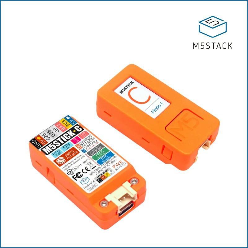
03/03/2021 at 03:39 • 0 commentsAt this point in my thinking, I was pretty solid on wanting a wireless solution, and using something that acted like a keyboard seemed promising when married with AutoHotKey. The natural DIY solution was an ESP32 because of its in-built wifi and Bluetooth. One of those in a nice little case with some buttons outside and battery inside sounded about right. But, hey, wait ... I've already got something like that. M5Stack's M5StickC.
It's got a 95 mAh LiPo battery, a USB C charge/serial port, a 160x80 TFT display, a couple of buttons, and some other goodies that might or might not be interesting for this use case. You can get these for US$10-15, and I already have a couple right here. I've done some experimenting with them and found them pretty easy to work with. The M5Stack company's documentation and examples are pretty good.
It's about the size of 2 LEGO bricks stacked on top of each other. If that's too small for your hand, or if you want more battery life, M5Stack also sells the M5StickC 18650C, which is a sort of wand with a LiPo battery into which the M5StickC can be fitted.
![]()
Sometimes the simplest-seeming things hide considerable complexity. If you use the USB C port or run the Bluetooth samples from M5Stack, they both act as simple serial communicators. I can remember back in the days before USB and PS/2 connectors when some keyboards just sent characters over an RS232-like connection. You typed a character, and it sent that character. If you held down the Control key and typed a character, it sent a control character (or nothing if the key you pressed was in the wrong place in the ASCII table). If you held down the Alt key and typed a character, it sent the character with the high bit set. Times were simple, indeed.
With the advent of USB standards, or maybe a little before, keyboards and mice were specifically recognized as those kinds of Human Interface Devices (HIDs), and they spoke a more elaborate protocol that allowed for more flexible interactions over a standardized protocol. A keyboard sends what is commonly called a "scan code", which generally represents a particular physical key. Along with that scan code, it also sends the current state of modifier keys like Control, Alt, Shift, charm, spin, damage, health, and ... (wait, that can't be right).
What all this means is that you can't just feed characters over a serial connection and expect things to work on a modern PC. Luckily, there is an Arduino USB keyboard library, and someone called T-vK has taken the trouble to adapt that into an ESP32 BLE Keyboard library. I've tried that BLE keyboard library with the M5StickC for enough to know that it gets recognized as a keyboard and can send characters to the PC it's paired with.
-
The key to muting
03/01/2021 at 00:06 • 0 commentsIt's pretty typical for mainstream keyboards to have keys that do media controls. With those keys, you can pause or resume a video or audio track, you can turn the volume up or down. You can also do a few other things, like launch a web browser or your email application.
One of things you cannot do is mute your microphone. Sure, there is typically a mute button, but on a computer it has a different meaning than it has on a telephone handset. On a telephone, muting means muting the microphone. On a PC, muting means muting the audio output from the speakers.
At first, this lack of keyboard code for muting the microphone seemed like a weird oversight to me. I thought maybe I just hadn't looked in the right place to find that keyboard code. Well, by now I have looked in the right places, and there simply isn't one. I don't know where they were originally defined, but those special keyboard codes are listed in HID Usage Tables FOR Universal Serial Bus (USB). Likewise, the Bluetooth HID profile builds mostly on the USB HID profile, so it has the same keys defined. In fact, the Bluetooth Human Interface Device Profile 1.1.1 simply references the USB usage tables.
All of that goes to show that it's not a mistake that keyboards don't have such keys, except maybe in special cases where the manufacturer has gone to some extra trouble (maybe on some laptops). Likewise, it's not a mistake that operating systems don't provide a driver to listen for such a code and mute the microphone. It's the same situation for turning the camera off and on. Instead, it's up to applications to control those devices while leaving management of the speakers to the operating system. OK, I still think it's an mistake, but it's a standards-based mistake.
The computer I use regularly for video meetings is a laptop provided by my day-job company. They are pretty serious about security, including supply chain security. So, even though I have reached the lofty level of Great Exalted Rhubarb in a software development organization, my laptop is pretty locked down. Any solution that required some kind of special driver could lead to an extra layer of hassle in going through an approval process to get it green-listed for my laptop. I have other things to do with my time (I was going to say better things, but I don't want to start an argument).
![]()
The laptop runs Windows. I'd hesitate to call that lucky, but one of the lucky things is that the very popular AutoHotKey utility is already approved for my use. Although that's a Windows-only application, I guess there are kinda-sorta equivalents for Mac and Linux. In a nutshell, AHK can intercept just about any keys that an infinite set of monkeys at typewriters could produce, and it can then take a scripted action. Scripting encompasses a pretty wild set of possible activities.
This mostly solves the PC-side software problem for me. If I can have a device that acts like a keyboard and produces keyboard codes that won't interfere with something else, I can have AHK intercept those keyboard codes and do the things I want to happen.
This flexibility also solves a user interface problem for me. What's the state of my microphone muting? If I simply use one keyboard code as a toggle, I don't really know if the microphone is currently muted or not. Instead, I can use one keyboard code for muting and a different keyboard code for unmuting. Contrast that with the standard keyboard code for muting the speaker. It's a simple toggle, which in practice is OK since you hear or don't hear the audio to know the state (or you are sitting in front of a screen that has some kind of visual feedback).
-
Beken BK2535
02/28/2021 at 02:21 • 1 commentThere is a family of "Smart TV" remotes available from Chinese sources for US$10-20 that are actually wireless keyboards. They look more or less like a TV remote on one side, but when you flip them over, they're full (more or less) QWERTY keyboards. I say more or less because they may be missing the Fn function keys along with key modifiers like Control and Alt. The intent is that you can type passwords or search box entries or whatever.
Here's a picture of a typical example, which the manufacturer calls an "Air Fly Mouse". It's available with or without a microphone and with or without backlighting. If you plug the dongle into a PC, you will find that the PC recognizes it as a keyboard, and most of the buttons do normal things. By normal, I mean that the keys send the same codes as you would expect if you had a traditional keyboard with those special keys (media control, and so on). That's confirmed by the slender instructions that came with it. Apparently most smart TV-related devices are expecting that. Handy.
One of the things that is pretty cool about these devices is that they have a gyroscopic motion sensor that lets you move an on-screen mouse just by manipulating the remote. I'm not too interested in that, but I tried it out with an Android TV box. It worked surprisingly well. You have to turn the mouse on/off because it uses more power when the gyros are active. With the gyros off, the MCU is probably sleeping and only wakes up when a button is pushed.
![Image 1 - MX3-2-4Ghz-Wireless-Air-Fly-Mouse-Remote-Control-6-Axis-Inertial-Sensor]() I wondered if I could use this directly or reprogram one for my own purposes. So, after I got one, I almost immediately took it apart. It has no branding or FCCid on the outside. The circuit board was marked with "TYX-MX3v1.6 20190401 2019.6.6". That led me the the web site of Shenzhen TYX Technology Co., Ltd. I was not too surprised to see that the board had pads for a microphone and a dozen or so LEDs for backlight (I bought the cheapest model, and it doesn't provide either). Even though it's not marked anywhere that I could find, I was able to find by searching around that a very similar device has FCCid 2AF3EMX3-V, which in turn leads to a user manual of sorts via fcc.gov (or the slightly more accessible fccid.io mirror site). The user manual describes itself as a requirements document. It's from 2015, so not an exact match for the current devices, but it's probably close.
I wondered if I could use this directly or reprogram one for my own purposes. So, after I got one, I almost immediately took it apart. It has no branding or FCCid on the outside. The circuit board was marked with "TYX-MX3v1.6 20190401 2019.6.6". That led me the the web site of Shenzhen TYX Technology Co., Ltd. I was not too surprised to see that the board had pads for a microphone and a dozen or so LEDs for backlight (I bought the cheapest model, and it doesn't provide either). Even though it's not marked anywhere that I could find, I was able to find by searching around that a very similar device has FCCid 2AF3EMX3-V, which in turn leads to a user manual of sorts via fcc.gov (or the slightly more accessible fccid.io mirror site). The user manual describes itself as a requirements document. It's from 2015, so not an exact match for the current devices, but it's probably close.There are only two chips on the board. A pretty small chip has the marking "ISA 36FA 349". That didn't lead me to anything, and I'm not actually sure it's a chip. It could be some kind of discrete component related to the radio or power conditioning or something, and it just happens to look like a tiny chip. The other chip, of a decent size, was marked "BEKEN BK2535 DH8401S". That led me to this BK2535 product overview. It's an SoC with an 8051-compatible MCU and 32k of flash. That it has flash is pretty promising, but the detailed datasheet and any information about interfacing to the chip is not publicly available. The Beken company keeps them confidential. In the 21st century, I could probably find the technical docs somewhere with enough diligent scouting around, but I don't want to spend that energy and ethical karma.
Even without the effort of figuring it and out and reflashing it, I might still be able to use one of these remotes for this project because some of the keycodes that it can send are off the beaten path, like Fn keys that are F13 or above. The batteries would last forever, and the device has a nice manufactured look (though a slightly flimsy manufactured feel). The buttons are the typical silicone mat with plungers that push on tiny foil switches. I would still have to remember which buttons did the things I wanted, and I'd have to avoid accidentally pushing any buttons that did other things. So, interesting but not ideal for this use.
-
Ab initio
02/25/2021 at 17:15 • 0 commentsWhen I first started idly thinking about this, I wasn't yet at the point of wanting something wireless.
I thought I might get one of those keyswitch testers and modify it to act like a tiny keyboard. That would be a lot of work and would probably look like a porcupine with lots of wires and things hanging off of it. I'm glad I didn't pursue that very much, because....
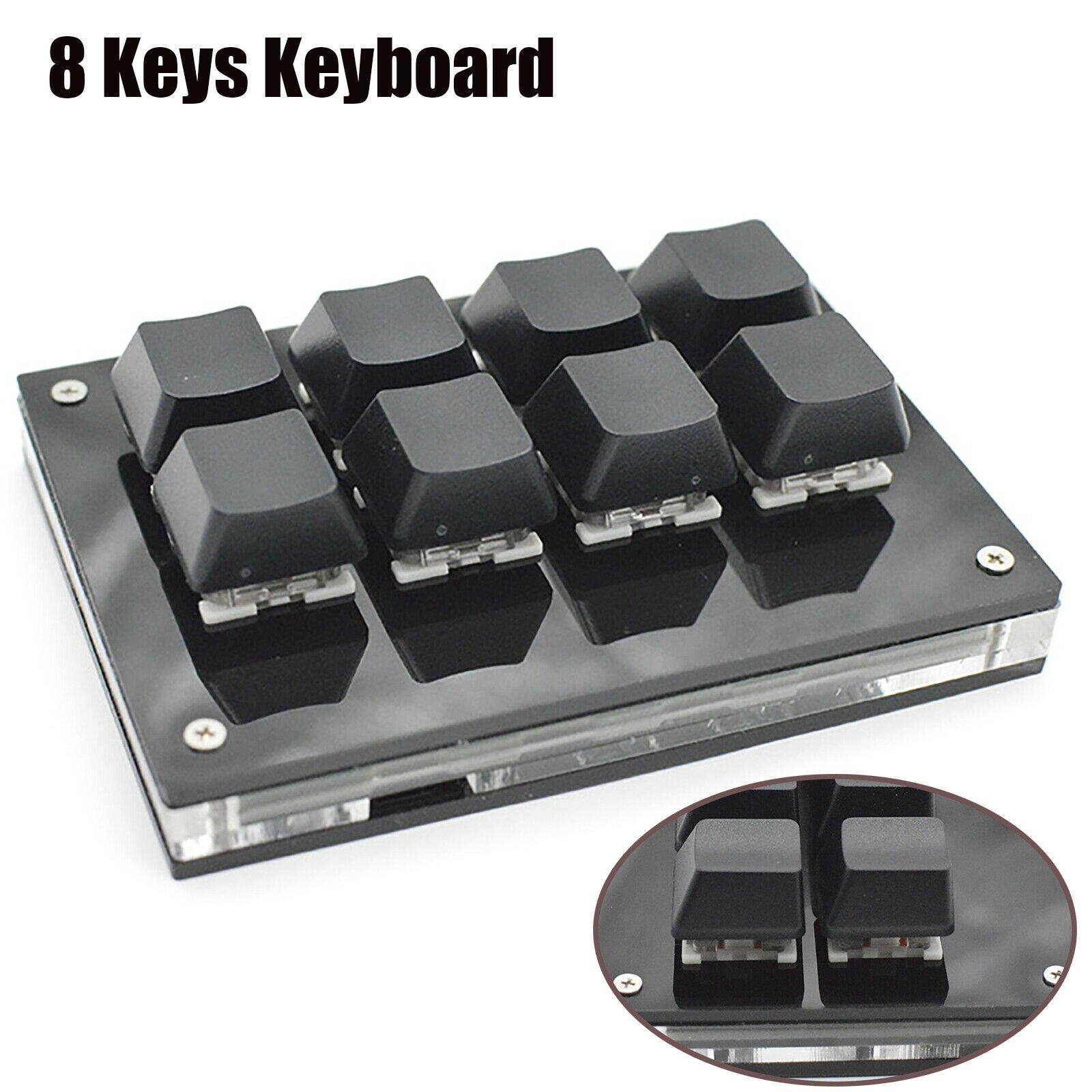
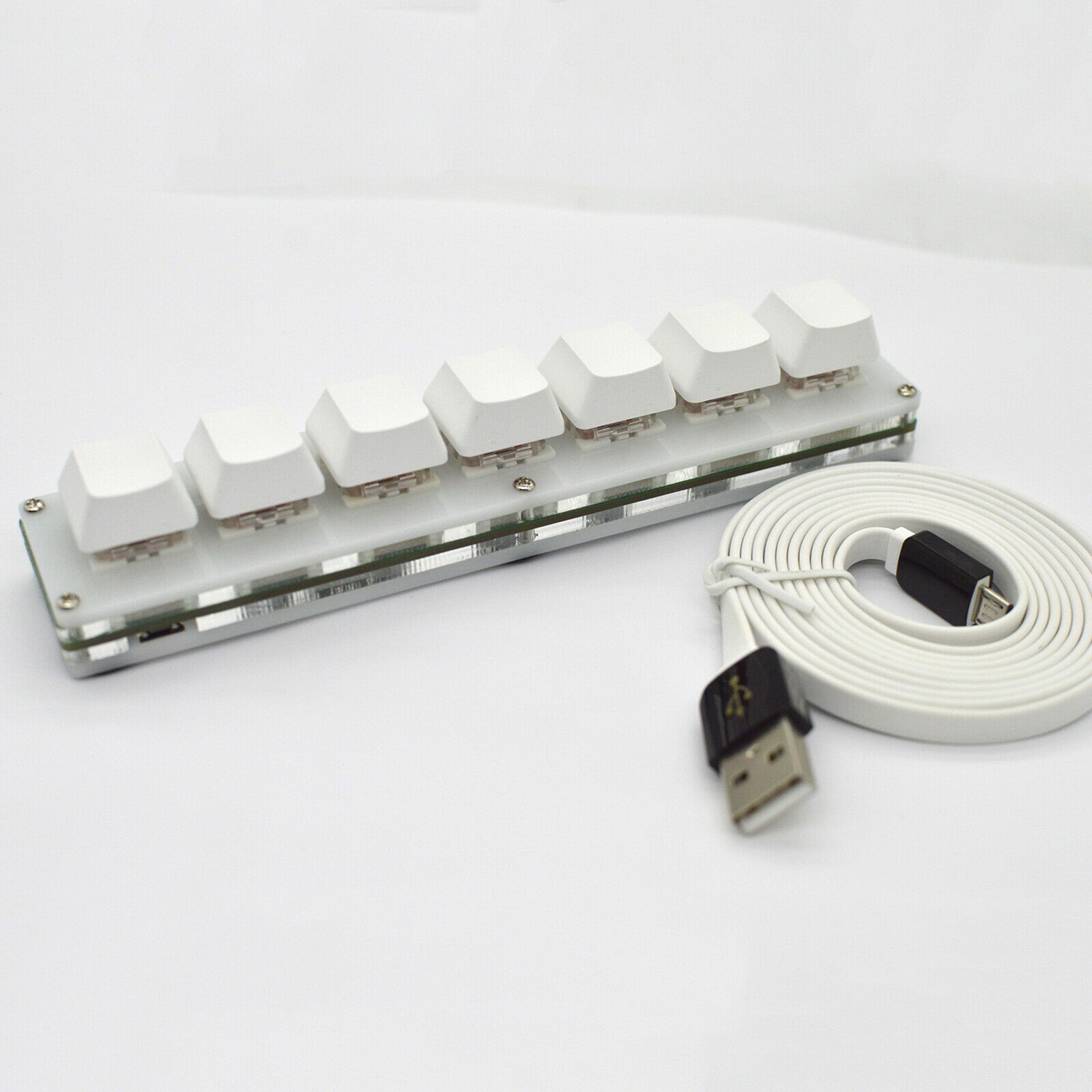
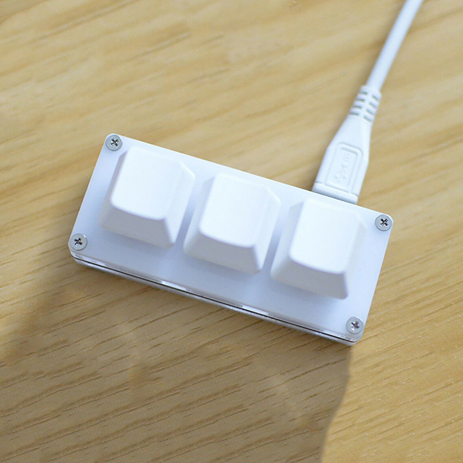
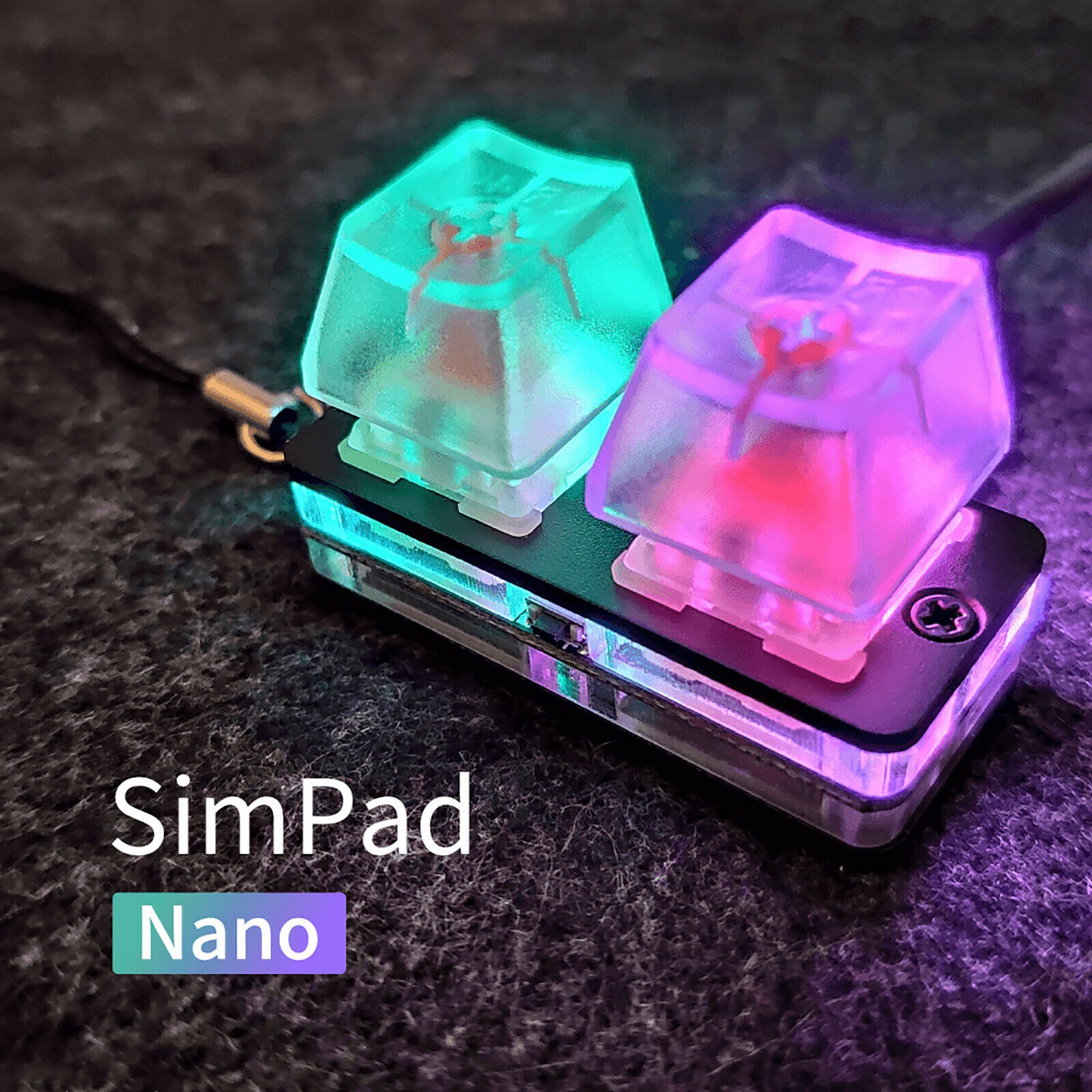
There are plenty of off-the-shelf and DIY "stream decks" for use with OBS Studio and other applications. Those are like small keyboards with 3, 5, 15, or however many buttons to which you can assign functions. Most of the interesting ones will let you assign custom keys or sequences of keys to any button so you can make them do your bidding. They cost only a few bucks (or many bucks if you are so inclined) and look like they are really well-made, but they connect over a USB cable. That rules them out for my (evolved) purposes. I might someday get one or two of these and take them apart to see if I could easily do something about replacing the guts to make them wireless.
Here are a few, not including custom-made stream decks featured on Hackaday or Instructables.
![]()
![]()
![]()
![]()
![]()
RemuterMCS
Remote control for muting and unmuting the microphone, camera, and speakers
 I wondered if I could use this directly or reprogram one for my own purposes. So, after I got one, I almost immediately took it apart. It has no branding or FCCid on the outside. The circuit board was marked with "TYX-MX3v1.6 20190401 2019.6.6". That led me the the web site of