 greg
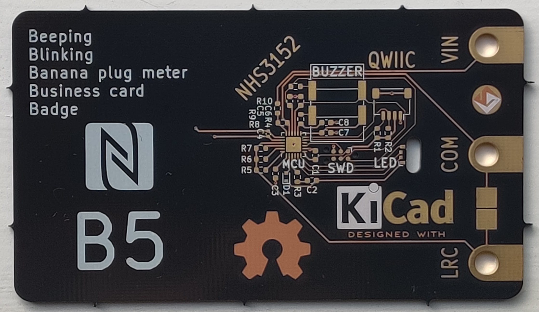
gregMy progress been delayed by samples getting stuck in customs. I would have preferred to have tested out the design before sharing more, but I can at least provide some of the theory of the design that I ordered from OSH Park. It looks really good in after dark.
 Here is the schematic for the design:
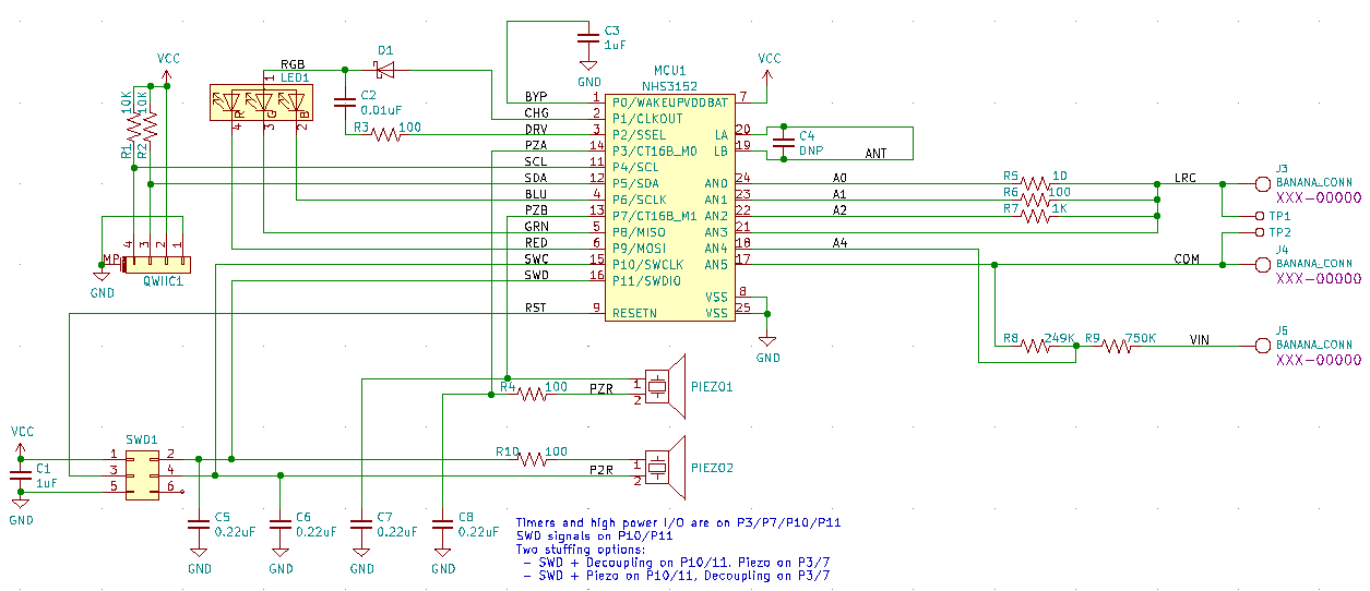 As I mentioned in the last post, I included two buzzers as a stuffing option. You can see how they overlap in the picture of the board.
Another interesting thing to note are the three resistors, R5-7. These are another stuffing option I will be testing. As shown they are three different load resistors that I could use for impedance measurements. I am hoping that the loading of the current to digital circuit will be sufficient for my measurements so that these are not needed. If they are not needed as loads, I may use them as reference values for calibrating the impedance measurements. I expect reference impedances will be more useful than the programmable loads.
The current to digital circuit measures current integrated over time which is perfect for counting coulombs into a capacitor. The voltage rise per coulomb is proportional to the capacitance.
Discussions
Become a Hackaday.io Member
Create an account to leave a comment. Already have an account? Log In.