 Krists
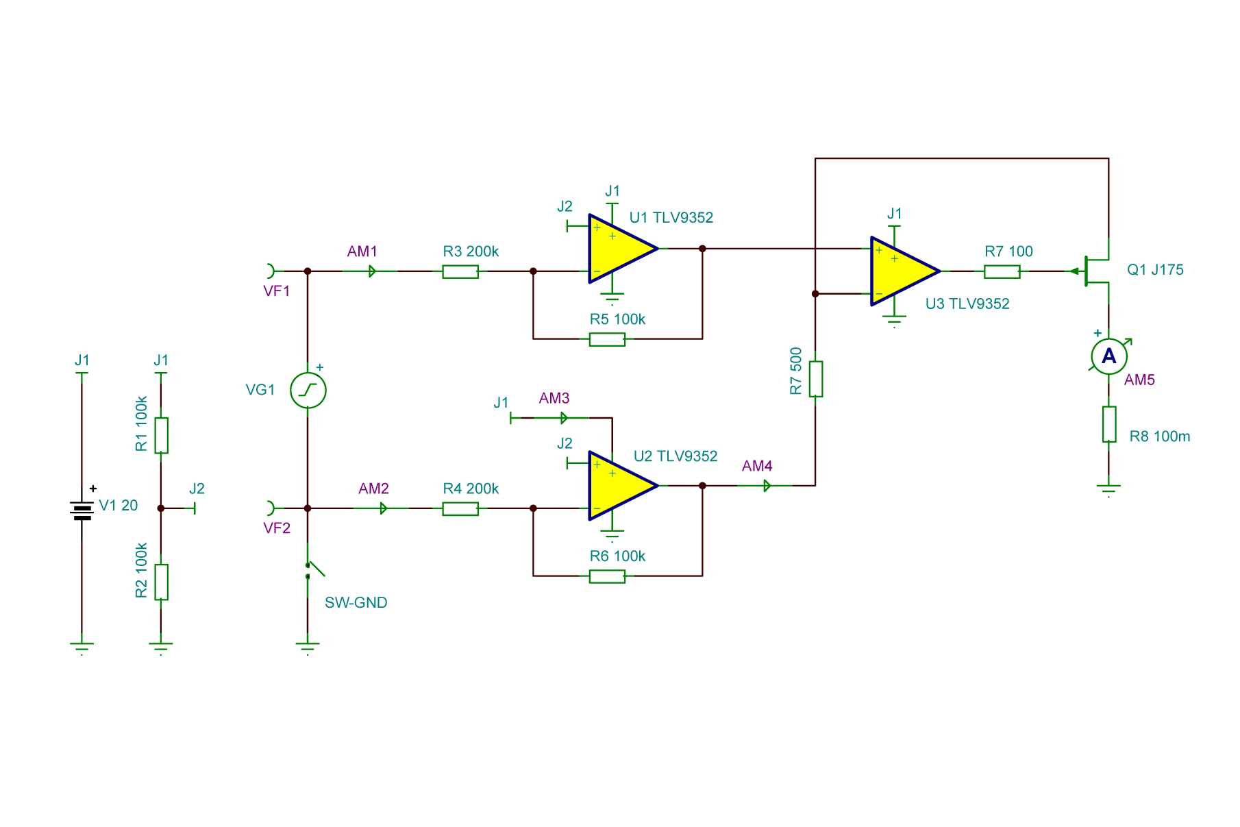
I suppose to build the circuit around Texas Instruments TLV9352 opamps and P-channel JFET transistor. TLV9352 opamps are listed surprisingly cheap with wide operation voltage up to 40V and good current sourcing capability.
Specs of the device would be:
Input (measured) voltage up to 40 V that should be matched with power supply for the device. Like, to convert 20V input (referenced to negative rail or differential / floating) 20 V supply should be used.
1:1000 voltage to current ratio. 1V input will source 1 mA to output, 10V will source 10 mA and so on. Probably additional 1:100 range can be used for input voltages up to 4 V. For that some jumpers (not nice) or relays (nice clicking) can be used.
Conversion precision: ±0.5 %. Bandwidth: up to 1 Mhz. Can convert only positive voltages with + input more positive that -.
Discussions
Become a Hackaday.io Member
Create an account to leave a comment. Already have an account? Log In.