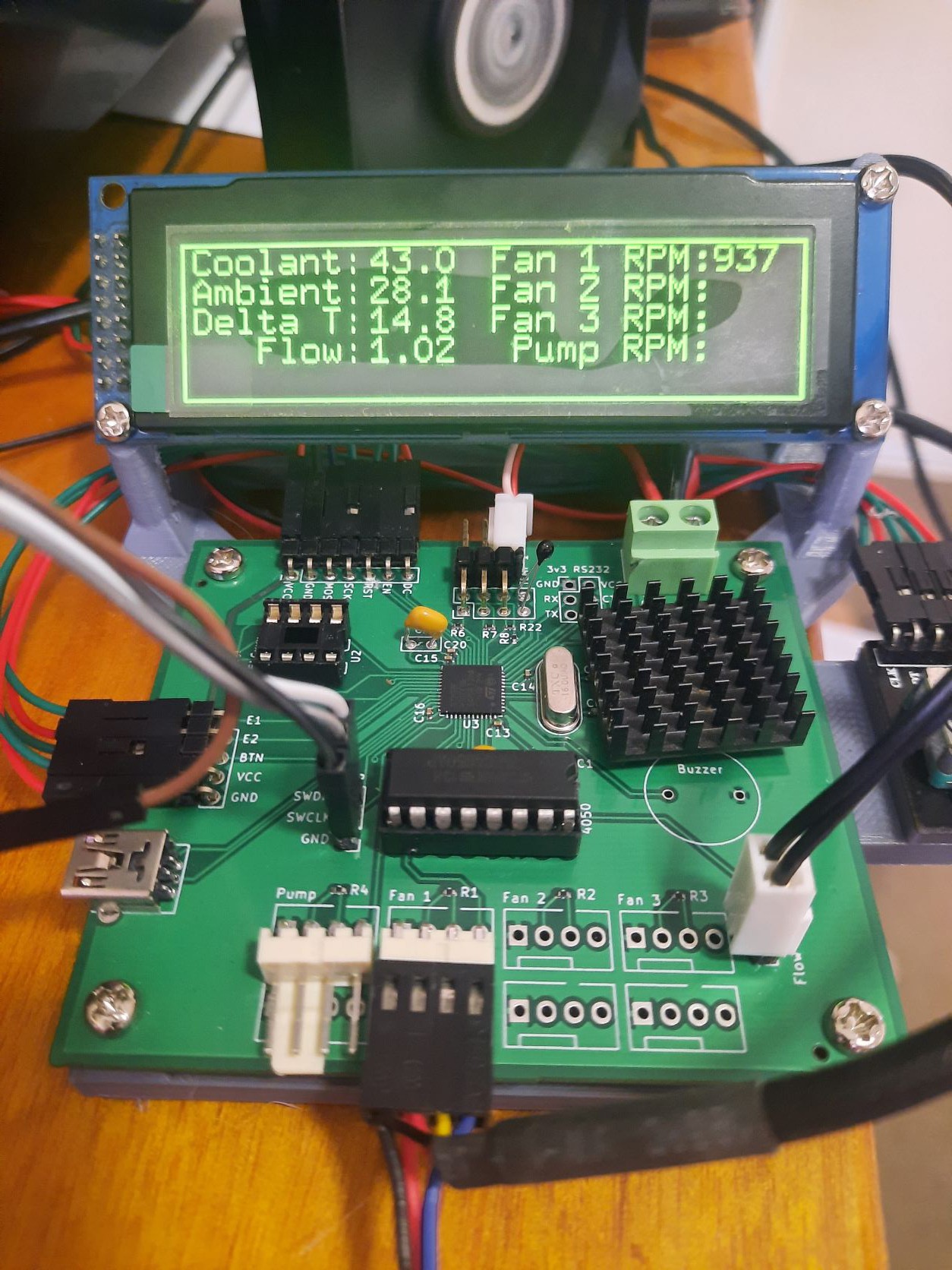
I've got some PCBs made at JLCPCB. There's a couple of minor goofs in the PCB design, but nothing too major.
- Not enough ground pins for the unused LCD pins that need to be tied to ground.
- LM317 voltage regulator gets pretty toasty. I need to swap that out for a switchmode regulator.
- Pin header alignment is bad in a lot of cases.
- Flow rate sensor should probably be connected to TIM5 instead of TIM3.
None of these are too much of a problem and easily worked around for the time being, they can be fixed in the next revision of the PCB.
For now I'll be continuing developing the firmware. There's still lots more to do.
Discussions
Become a Hackaday.io Member
Create an account to leave a comment. Already have an account? Log In.