 Tijl Schepens
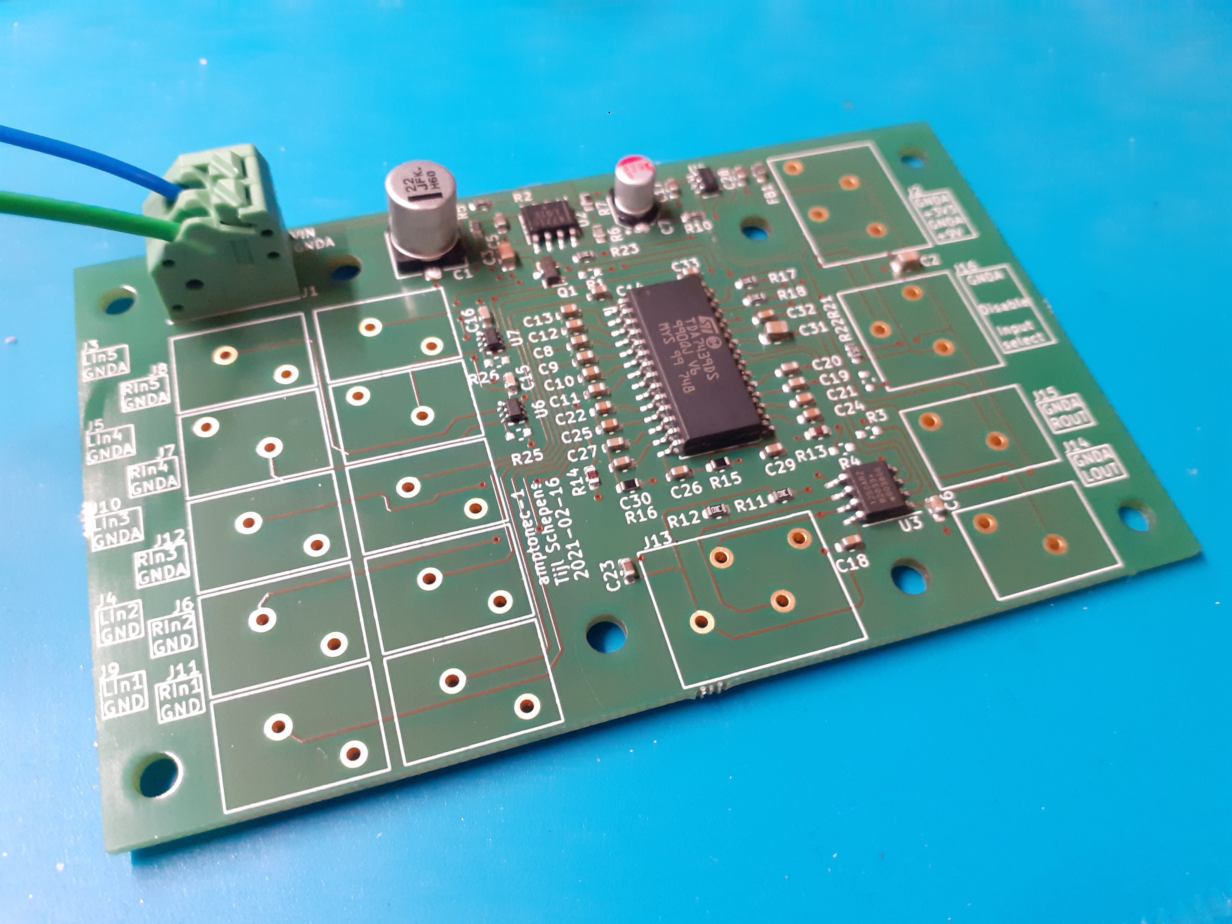
So today I finally got around soldering the board.
A first power-up shows that the 9 V and 3.3 V LDOs are working as expected. It also shows that I made a stupid mistake...
I added R23 in the schematic and populated it thinking that if the gate of the transistor is pulled to 3.3 V, the regulators would be disabled by default. Of course that cannot work as you cannot generate 3.3 V if you disable the regulator (duh!).
So instead either R1 has to be populated to enable all regulators by default, or an external pull-up from another 3.3 V supply needs to keep the gate high to disable the regulators.
So now that the board is soldered and the regulators are ok, I can fire up my Raspberry Pi and see if the I2C is working. Fingers crossed!
Discussions
Become a Hackaday.io Member
Create an account to leave a comment. Already have an account? Log In.