 Darrin B
Though it has been only a few weeks since the last log entry, there are many developments to write about this time.
- 0 Hz to 20 Hz fail
- 741 * 3 + 555 = WWVB receiver
- TTL + 741s + 1970's ADC + i4004 = SDR?
- More wire-less at 1/50000 wavelength
- PCB loop antenna
- Strange scope sighting
0 Hz to 20 Hz fail
Getting an output that is logic level compatible was a compelling enough prospect that I continued work on the 0 Hz offset circuit. In the end, it turns out that an atomic clock is needed. Once synchronized to the transmitted signal, it would stay in phase and accurately generate the DC result. If I had an atomic clock, I could make an atomic clock. With that being the case, I switched to about 20 Hz. It would be easy enough to simply count the waveform peaks while comparing to a 0.1Hz reference oscillator. Finding an oscillator and divider combination to reach that target proved difficult using only parts on hand. Expanding the target range a bit finally yielded a 34 Hz result. An analog filter at a frequency this low takes a short while to stabilize when the input signal changes. The WWVB signal changes twice each second, and RF noise adds a few more changes to the mix. The resulting signal looked unintelligible. So, here ends the low-offset and no-offset frequency branches of the project.
3 * 741 + 555 = CW receiver
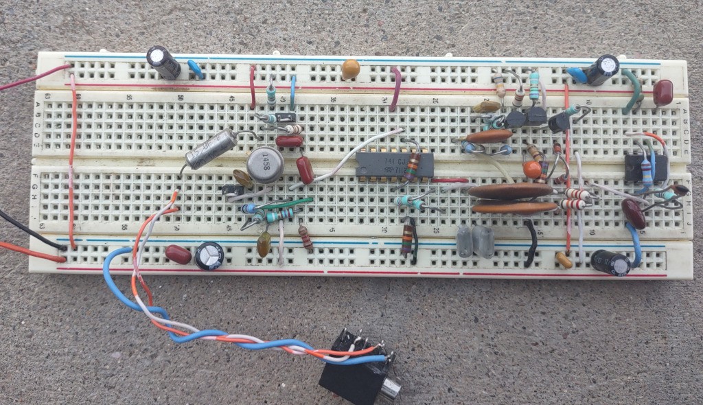
While working on the DC (0 Hz offset) system, I looked in to techniques for voltage offset compensation in op-amp circuits. I found an interesting quote about using the 741 op-amp in present day designs. The quote was "Don't." For the most part, I agree. It would be a challenge to find a current production op-amp that does not some, if not all, of the the 741's specs by at least an order of magnitude. However, using a 741 in a circuit would show that the circuit's builder could read and interpret the parameters listed in the datasheet. So I set out to build the "one chip wonder" circuit with 741s. First, it'll be a 4 chip wonder, since the 741 is a single op-amp per package part. No not yet. Even at +/-8.9V supply, there is nowhere near enough slew rate to generate the 60 kHz square wave to switch the mixer. Though a couple of TTL chips would get the job done, a 555 would be a more compact, and amusing, solution that would be running near it's voltage limit. Since I have just one 741 (with a 1971 date code!), the remaining op-amps are in the form of a 1458 dual op-amp since they are said to be "electrically similar" to the 741. Do you see a pattern forming? All parts for this build were available by the mid 1970s. The 3904 and 3906 appeared in databooks in the late 1960s, so there can be an active input section. For a first prototype attempt built from one 555, 2 diodes, 3 transistors, 3 op-amps and 30-some resistors and capacitors the result is a bit better than I expected. The WWVBeeps are audible and easily seen when viewed in Audacity. A Goertzel filter has no trouble turning the audio in to zeros and ones, should the output be digitized. But what ADC? With enough comparators, a flash converter could be built. However, that level of speed is not really necessary. It looks like this:
TTL + 741s + 1970's ADC + i4004 = SDR?
Can it be done? First, is there an 1970s era ADC capable of at least 6 bit resolution at 4000 (or a bit more) samples/sec? Next, how many int16 adds can a 4004 do per second? Also, is there bit-shift instruction available? Those parts, a few improvements to the 741 based receiver, and a proper TTL clock generator would result in a full-function I&Q SDR. Wouldn't that be a fun project? Any takers?
Back to the present
More wire-less at 1/50000 wavelength
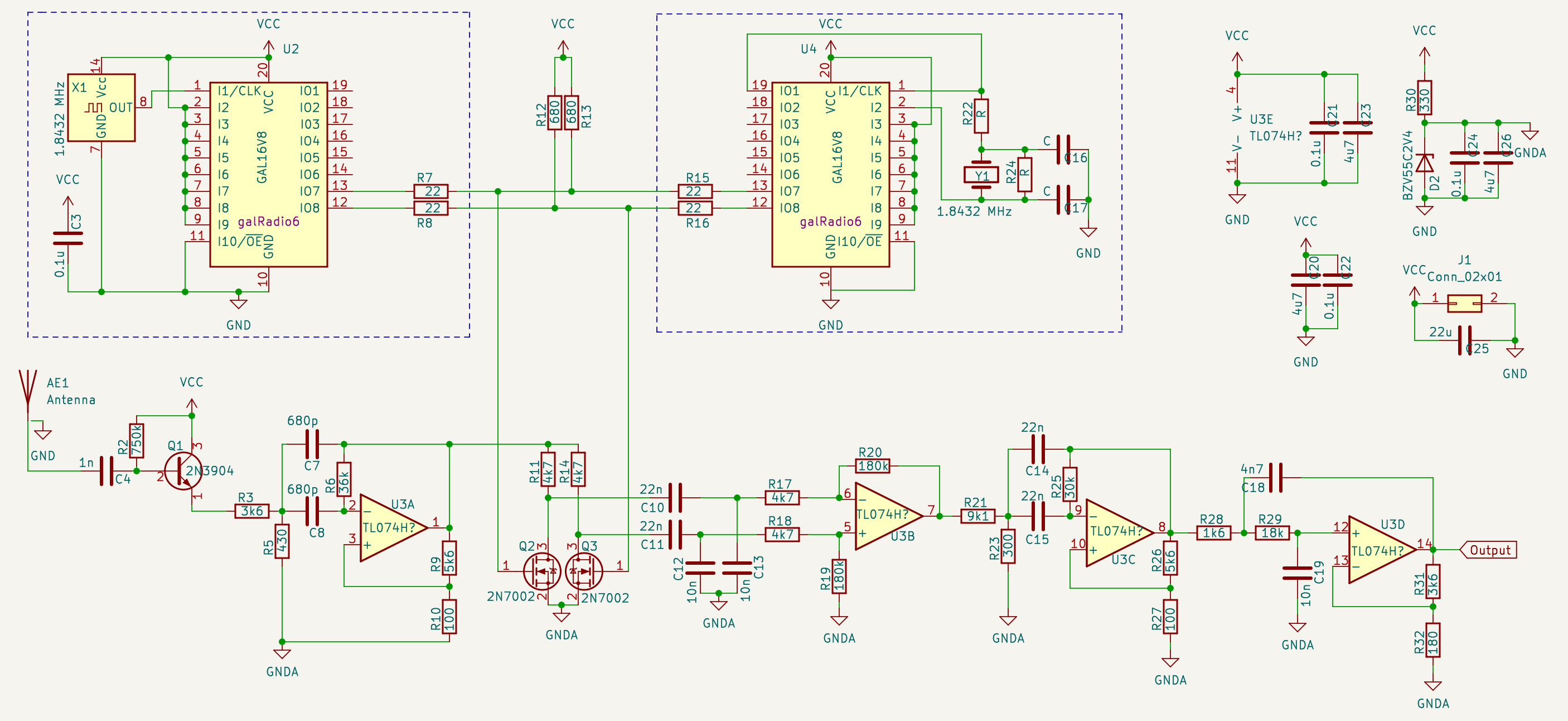
After giving up on the low/no frequency offset designs, I rebuilt the earlier 57.6 kHz circuit with some improvements. The most significant is that it is built with a 1.8432 MHz oscillator chip. It is used to eliminate the fiddling with picofarads to convince the crystal oscillator to work properly on the proto-board. Though the pc-board version will likely continue to use a crystal oscillator. The next upgrade is to the mixer's output low-pass filter, it is now a bandpass filter. We don't really need that 60Hz noise, do we? A brief addition to the circuit was a diode-transistor envelope detector, but it is unnecessary because of the aggressive analog filtering that removes the 57.6kHz component. Testing with the usual 6m wire antenna, the output caused heavy clipping at the sound card's input. Adding an attenuator brought that to a tolerable level. The next test was to try ever-shorter lengths of wire as the antenna. The output became inconsistent when a 75mm long wire was tested. Check it out:
GAL16V8
galRad6

CLK XAInA XAInB XBInA XBInB NC NC NC    NC    GND
/OE MXa   MXb   d     c      b  a XBOut XAOut VCC

;2x XOR, use one for Osc. with 1.8432 MHz crystal
XAOut =  XAInA * /XAInB
      + /XAInA *  XAInB

XBOut =  XBInA * /XBInB
      + /XBInA *  XBInB

;Compl. outputs at 57600Hz
MXa.R = a * MXa
      + b * MXa
      + c * MXa
      + d * MXa
      + /a * /b * /c * /d * /MXa

/MXb.R = a * MXa
       + b * MXa
       + c * MXa
       + d * MXa
       + /a * /b * /c * /d * /MXa

;Div 16
a.R = /a

b.R = b * /a
    + /b * a

c.R = c * /b
    + c * /a
    + /c * b * a

d.R = d * /c
    + d * /b
    + d * /a
    + /d * c * b * a

DESCRIPTION:
Self-contained oscillator and clock dividers to create signals for Tayloe demodulator. This one utilizes
source: 1.8432 MHz baud rate crystal
target: 60kHz (WWVB)
offset:    2400 Hz,
local osc: 57600 Hz (source / 32)
PCB loop antenna
If just a bit of wire hanging off of the proto-board is all that is needed, I could design that antenna right in to the circuit board. But why not something more suited to the task, a loop antenna? Well, I don't know how to design that kind of antenna. Yet. Another level of project within a project.
Strange scope sighting
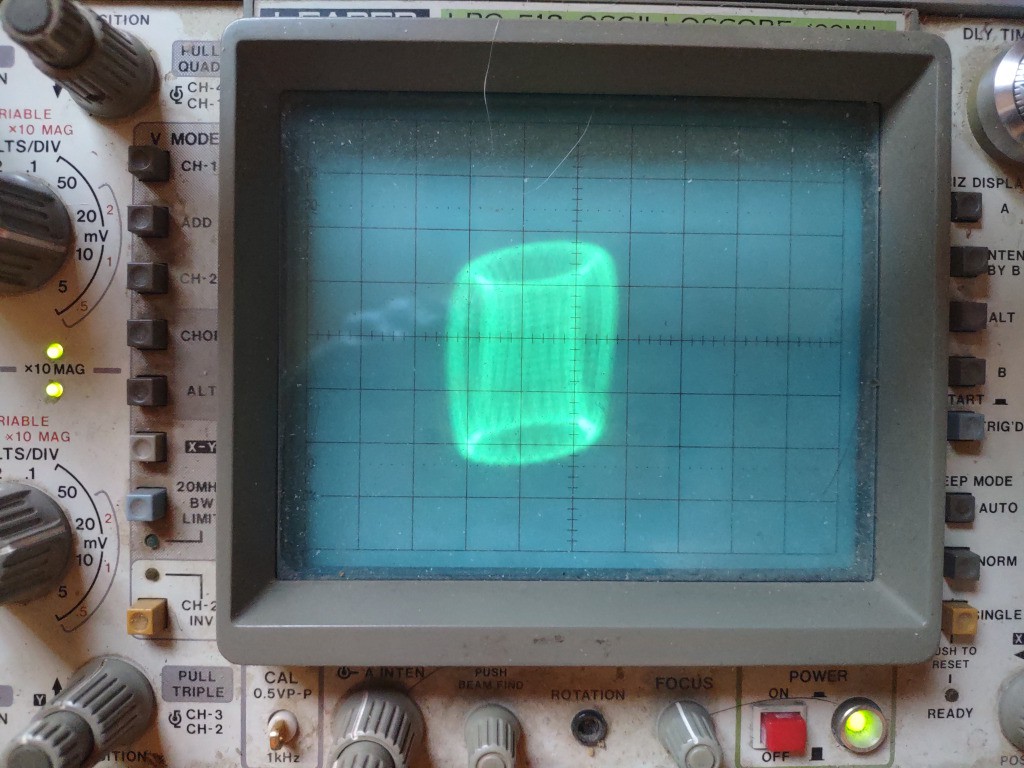
When the envelope detector was in place, I compared input and output to verify that it was working correctly, not clipping, attenuating the carrier and so on. Looking at the signals on the o-scope, I thought that the two signals might look interesting in X-Y mode. If you are not familiar with X-Y mode, it is useful for evaluating phase and frequency differences between signals or, with some simple external hardware identifying and testing components. Mostly, the mode is used to make interesting graphics and play Asteroids. I'll leave you with this photo.
Discussions
Become a Hackaday.io Member
Create an account to leave a comment. Already have an account? Log In.