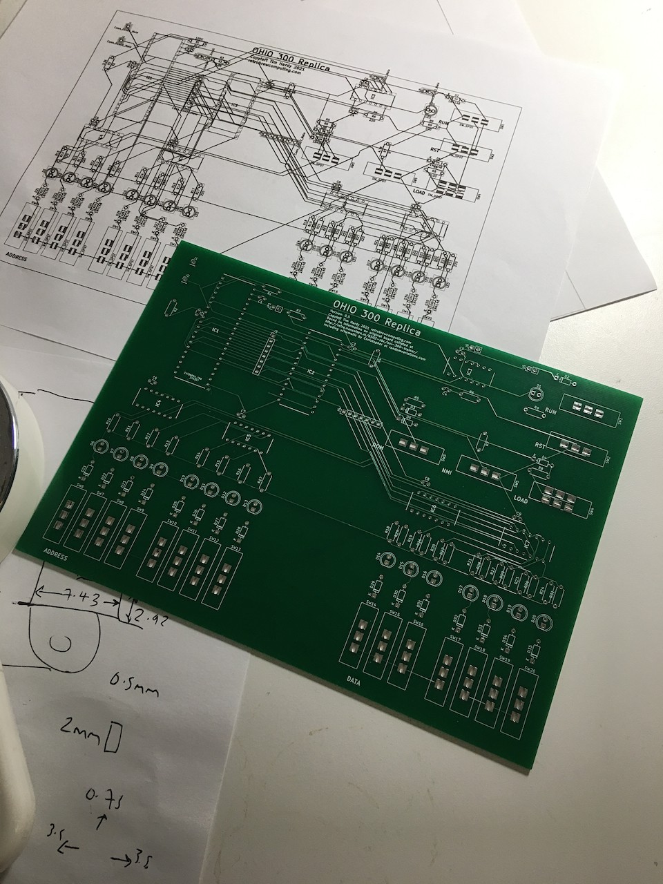
The first set of boards have arrived! I won't have time to add components and test this before the weekend but I have confirmed to my satisfaction that the footprints for the switches I designed are correct.

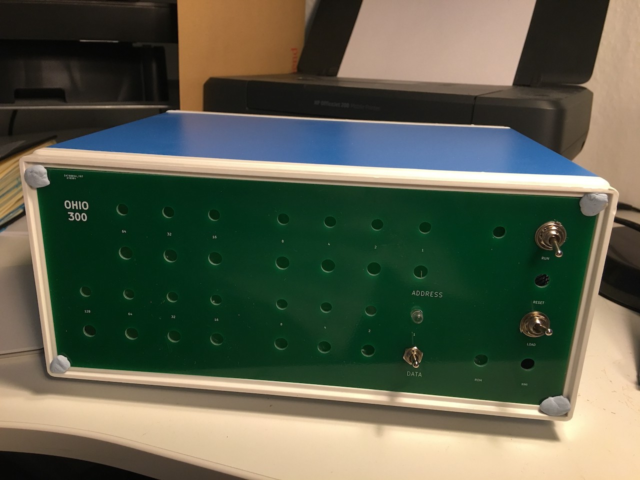
When I submitted the gerbers for manufacture, I also decided to whip up a quick front panel design in FR-4 as well and amortise the shipping costs. This will replace the front panel of 250 x 190 x110mm metal junction box, an enclosure that is large enough to hold the Ohio 300 Replica PCB.
I got the mounting screw hole size wrong - hence the blutak holding it in place - and will fix that in a later iteration once I have had a chance to explore any usability issues while using this. The switch and LED hole sizes though are mercifully correct.
This is intended as a quick proof of concept only and I'm immediately very happy with it. I think toggle switches on a vertical panel will be more fun than slide switches on the horizontal PCB and this set up will be good enough to play with until I finalise the design. I've ordered more toggle switches and am thinking about a second PCB to hold the LEDs in place.
First though I need to check that the main PCB works as intended. Updates to follow.
 Tim
Tim
Discussions
Become a Hackaday.io Member
Create an account to leave a comment. Already have an account? Log In.