 Timo Birnschein
This is a kind of temporary entry.
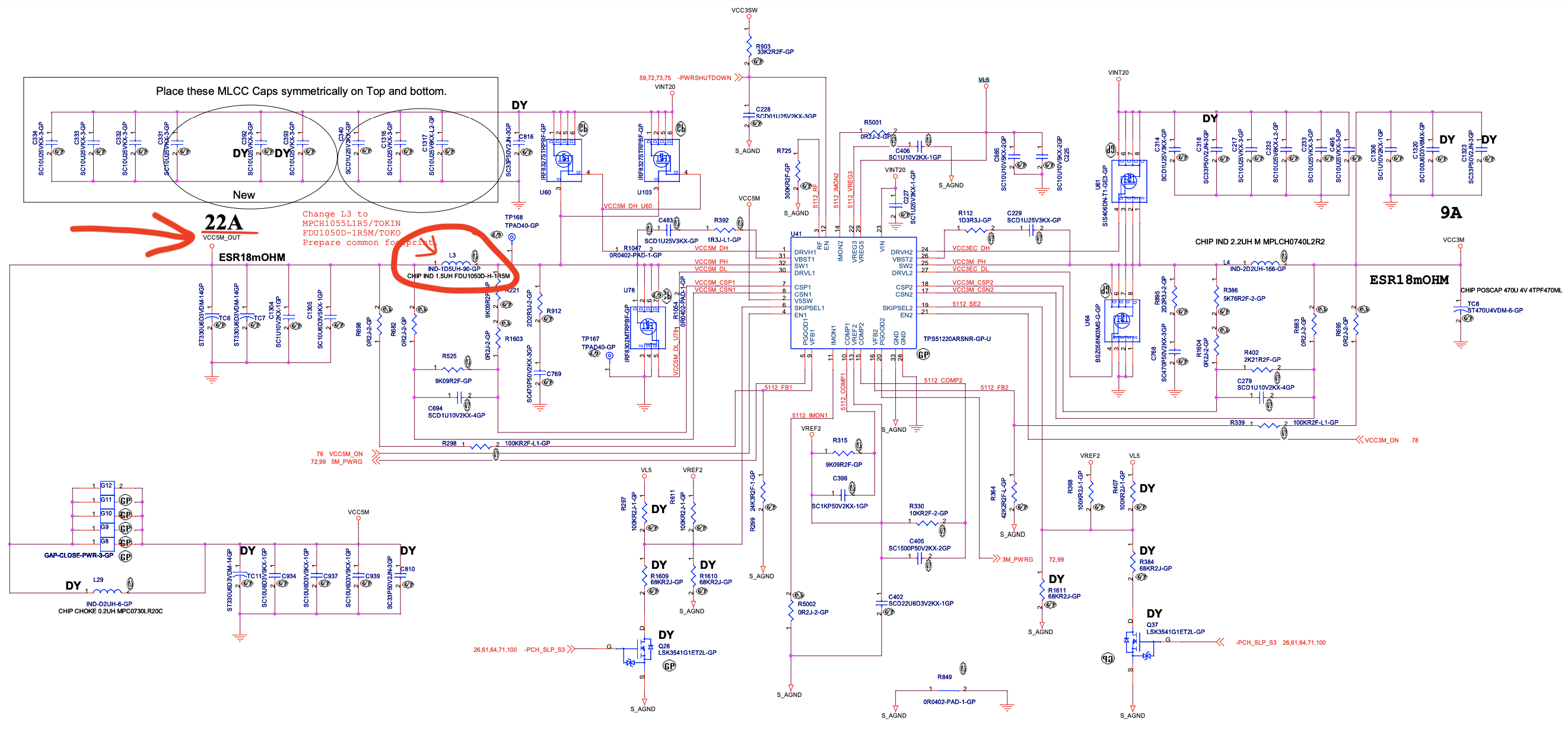
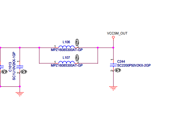
As can be seen above, on page 79 of the schematics (link in the comments below) seems to be the power distribution schematics. There are a couple candidates that are interesting here: VCC5M, VCC5B, and most importantly because likely switched with laptop power: VCC5M_OUT which can be had at the inductor L3. According to the documentation above the pin name it appears to be able to 22Amps. Seems like a lot and could mean that 1.5A might be available to my little Class-D amp. More on this later.
Looking at the board layout gives me L3 in a location that is covered by the magnesium frame. Magnesium. Metal. That's gonna hurt me at some point.
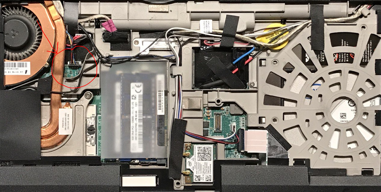
However, this board file viewer is really cool and clicking on the signal reveals where this signal goes! So I found these guys:
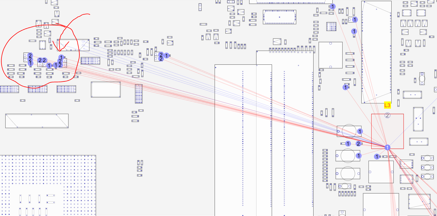
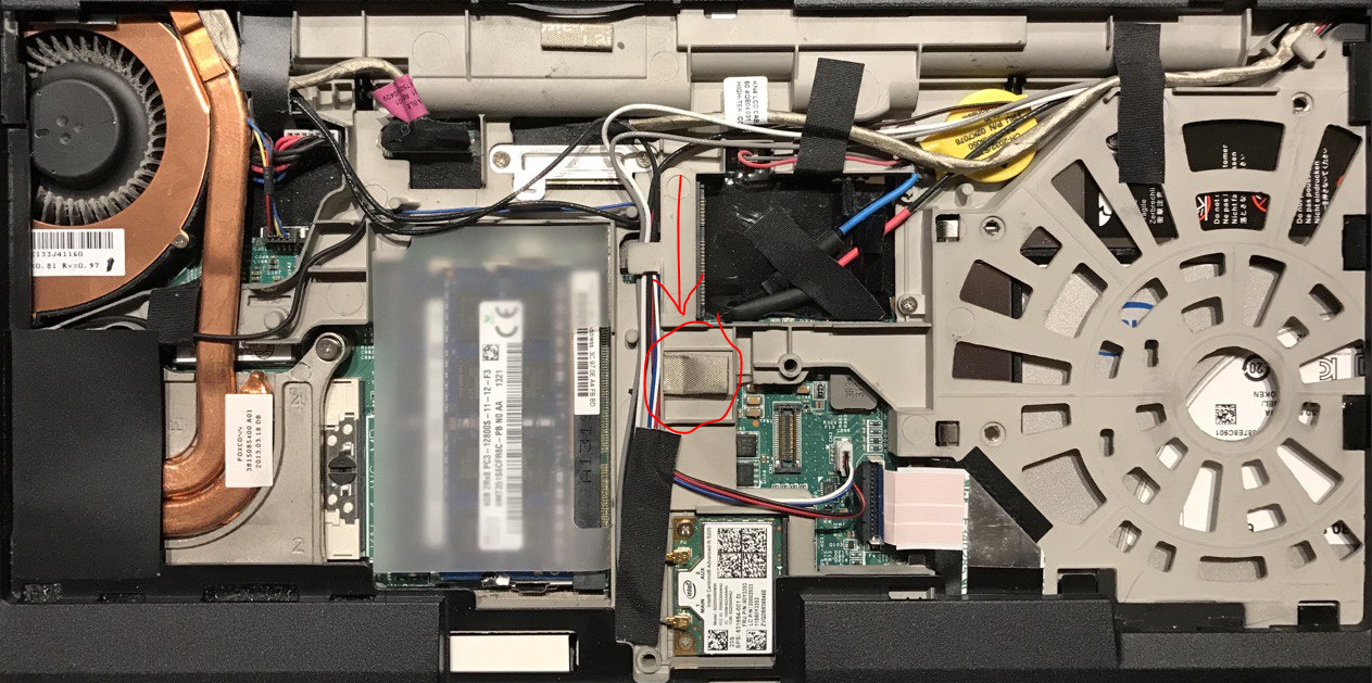
And these guys are located here:
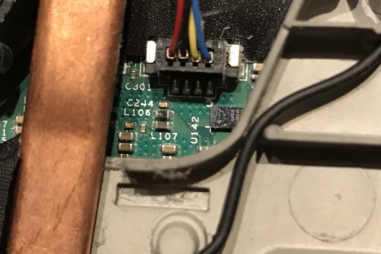
Happy as I am to find exposed and seemingly very well supported pins (lots of vias visible making these pins very good candidates) I take my multimeter out and start measuring. Sure enough, I find 5.17 volts and on the other sid/!@#$%^&POWEROFF
Discussions
Become a Hackaday.io Member
Create an account to leave a comment. Already have an account? Log In.