I've attached a link to my current schematic here which I've also uploaded to the project.
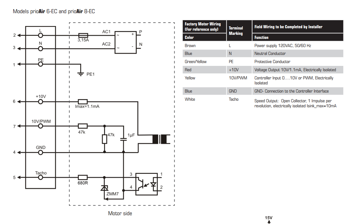
Additionally here is the interface schematic for the fan.
 Here is how I interface to it on the board:
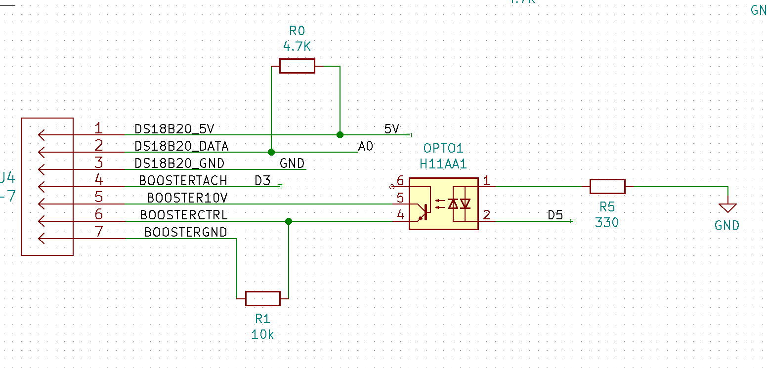
I am using the H11AA1 optoisolator on the 24VAC lines and also using another one (out of convenience) to drive the PWM signal for the 10v fan control line. The schematic does not show an optoisolator on the tach feedback circuit and I believe I need to add one as once this connection is made, the board stops working. Looking at my old test boards, I realized that the grounds were tied together between the fan and the Arduino. Attempting that now seems to lock the board up and it seems more straightforward to add more isolation. Not sure how it worked last time. Perhaps I just got lucky.
I have been using the same part number as I use for the AC lines out of convenience but should swap this to a DC component. Additionally to conserve board space, I'd like to get select a multi-channel component for this. Still through hole because I'm not set up or skilled enough for surface mount.
So that's Goal #1 for the next revision:
Fully isolate fan circuit with proper dual channel DC optoisolator component.
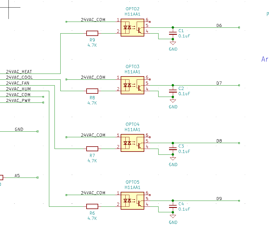
This is working as expected, however after moving to the EtherTen board and using Freetronics Protoboard Short as a footprint template, it would be much more convenient to be able to get these condensed into a single component. Additionally, I don't think I actually need the 4th circuit monitored but given that some thermostats have different levels of heat and cool for multi-stage systems, it would be convenient to be able to do that. Also, I don't think I'll be able to find a Tri-Channel vs a Quad-Channel so no reason to remove it at this point. Difficulty in this is finding a suitable product as my background in these things is pretty weak.
So there's goal #2 for the next revision:
Use a 4 channel optoisolator to handle the thermostat signals to reduce board space.
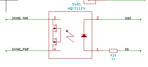
Here is a snippet over the fan override circuit. I have yet to test this but will do so prior to the next board being ordered. It would be convenient to find out if it doesn't work ahead of time, no? Anyone reading this that can tell me why this would not be able to safely switch 24VAC, I would appreciate feedback.
The EtherTen board I'm connecting this to has some issues pulling this off with the shield connected but works fine running the code without anything attached. I think the most glaring issue is the motor interface circuit at the moment. Additionally I have not used the temp sensor circuits at all. so that is not a factor yet.
Any help / wisdom / "WTF.. that is stupid" / guidance is appreciated. I have thick skin, go nuts.
Discussions
Become a Hackaday.io Member
Create an account to leave a comment. Already have an account? Log In.