 On a breadboard on my basement finally is a working revision of this. I had spun so many boards and wasted so many components i went back to basics....
I realize that an early schematic i made and had working must have been a stroke of luck because i never recreated the control and measurement I had at that time.
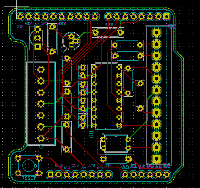
I intend to do a new PCB shortly that encapsulates everything. If that works on a traditional arduino, I'm going to try it on the EtherTen from Freetronics and try to get the ethernet communication side of the code up and running again.
Major changes I made:
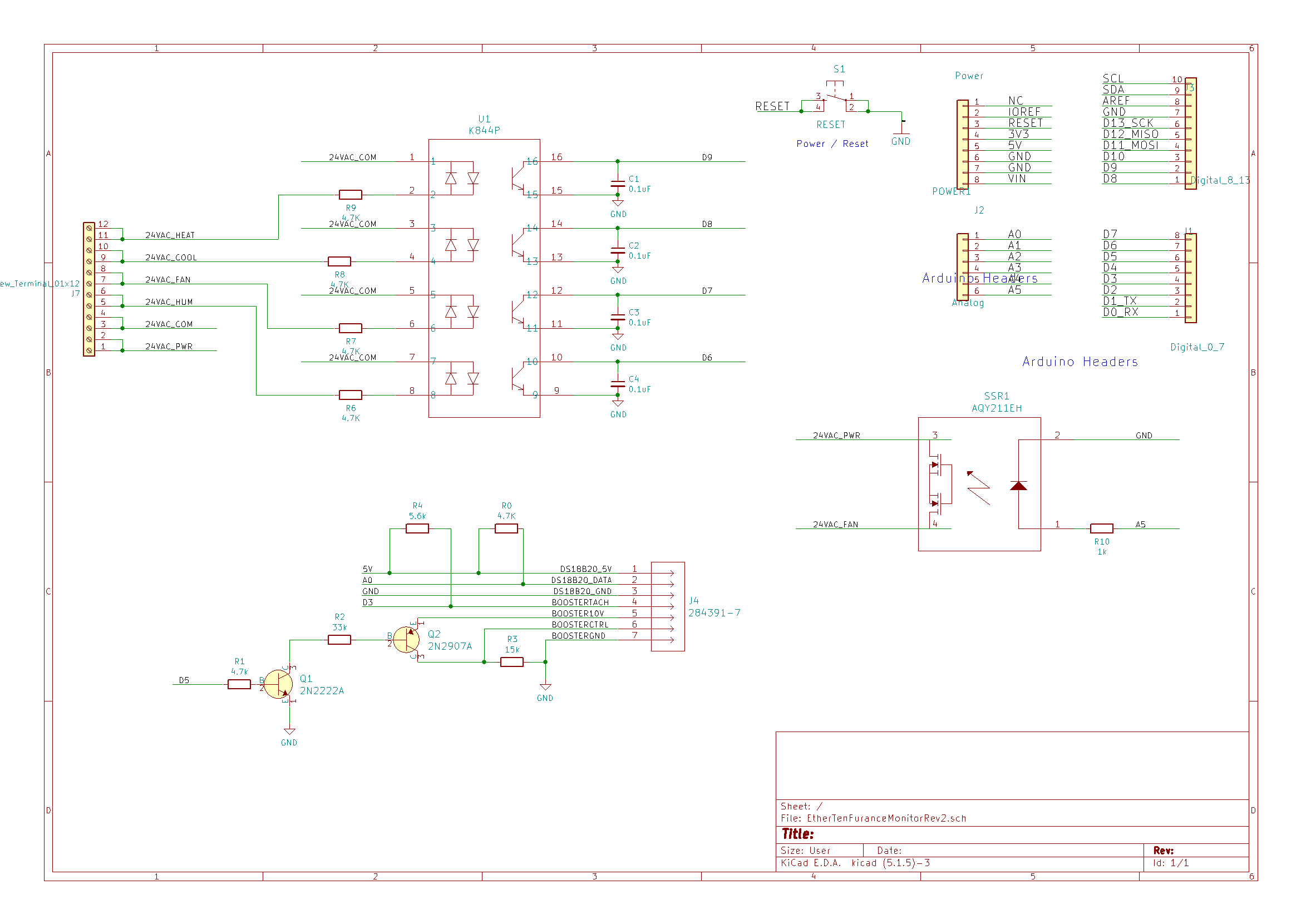
1. Consolidated my 4 optos into one component. Made board layout much tighter and compact.
2. I learned that since the fans onboard control circuit has its own isolation, there's little risk of issues or noise so there was no worry about hooking ground to ground between my fan controls and the 'duino. I feel the etherten might have been a little more sensitive but we will soon see.
3. Figured out that a little pull up help on the Tachometer circuit does wonders for a clean and reliable reading. I was using INPUT_PULLUP but it seems it's just a tad weak.
4. Instead of jamming my thermostat wires into a terminal block and Tee'ing off of them in an attempt to share conductors, I decided that I'm going to have my board pass the thermostat signals across it. At the moment I've doubled the moment of screw terminals and bonded the adjacent terminal to minimize the amount the ac signals traverse the PCB.
Does it work? Yeah it appears to.
Did i learn stuff? Sort of. The open collector circuit on the fan i still don't 100% grasp the purpose of all the components on the fan side but i don't think that matters.
Discussions
Become a Hackaday.io Member
Create an account to leave a comment. Already have an account? Log In.