 John Lonergan
These boards work really well. Need to pick an appropriate resistor value for the LED and this requires experimentation; blue vs red s greem being quite different. The one here is using 1k and is red.
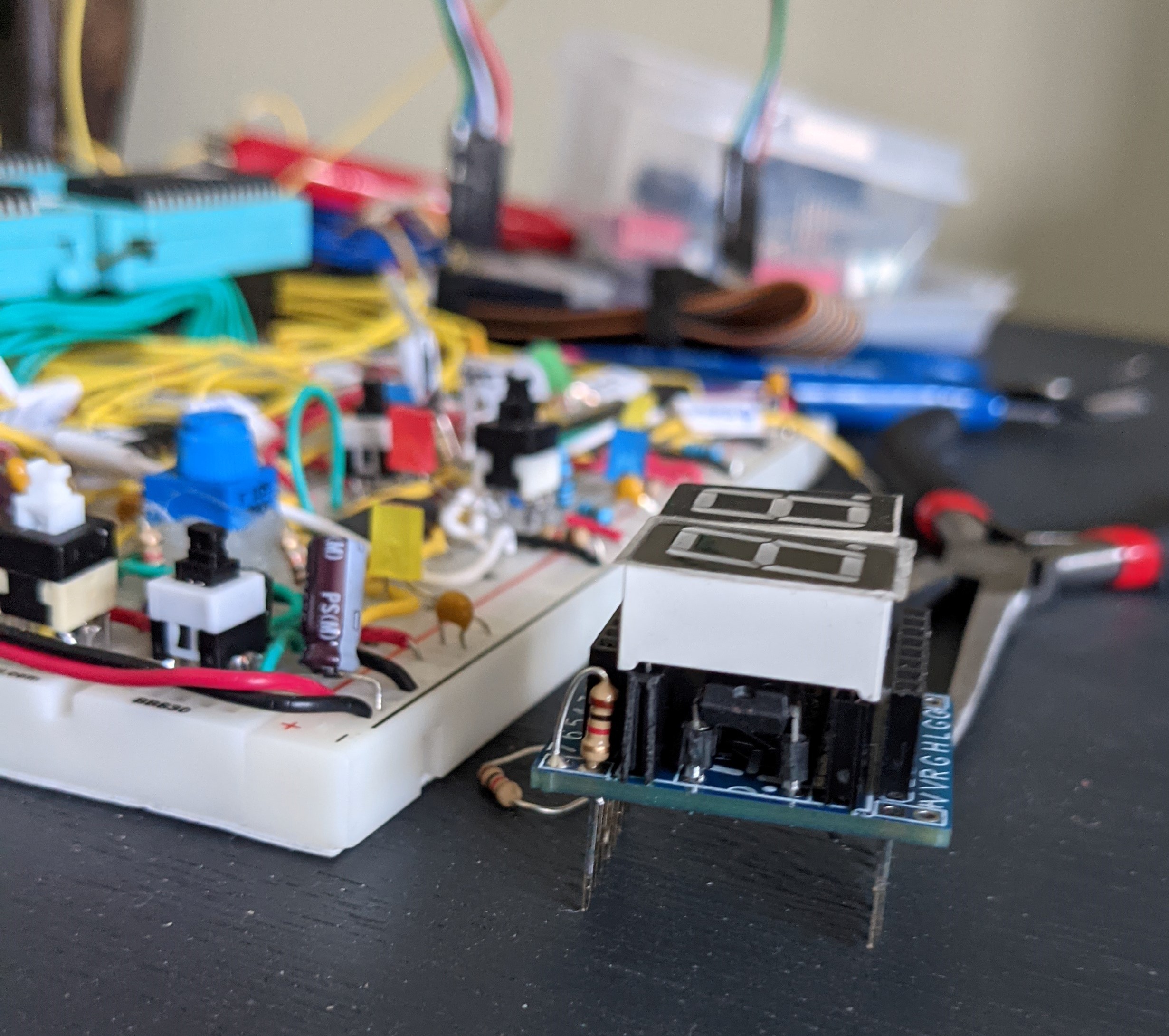
This setup gives me a really minimalistic dual 7 seg module that has no need of clocks or anythng like that so it's a great fit for my needs.
The PICs inputs have pullups turned on so when the inputs are disconnected or high-Z then it shows "FF".
I noticed that in use the hi digit seemed to flicker even though in testing the 8 input bits ought have been typically 0 or momentarily high Z. Also, when the bus was switching between some known values I noticed flickers on segments that should have been constant on or off.
I figured that the samplng rate of the PIC was seeing those high Z moments, or sampling half way though switching delays, and displaying unwanted values.
I "fixed" this by adding a loop to the code where it only changes it's displayed value if the value on it's inputs was stable for a millisecond (or something like that). This way short blips and switching randomness don't mess up the display. Given that the high-Z moments are very short.
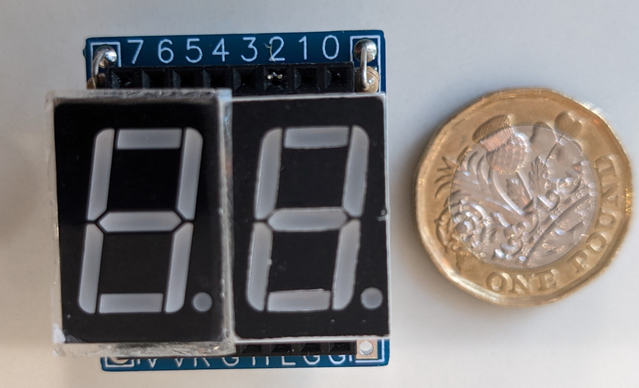
You can see what the V1 construction looks like here ...
The outline is pretty small.
The V2 board is in the post from China, but here's an image with the main points about the V1 board.
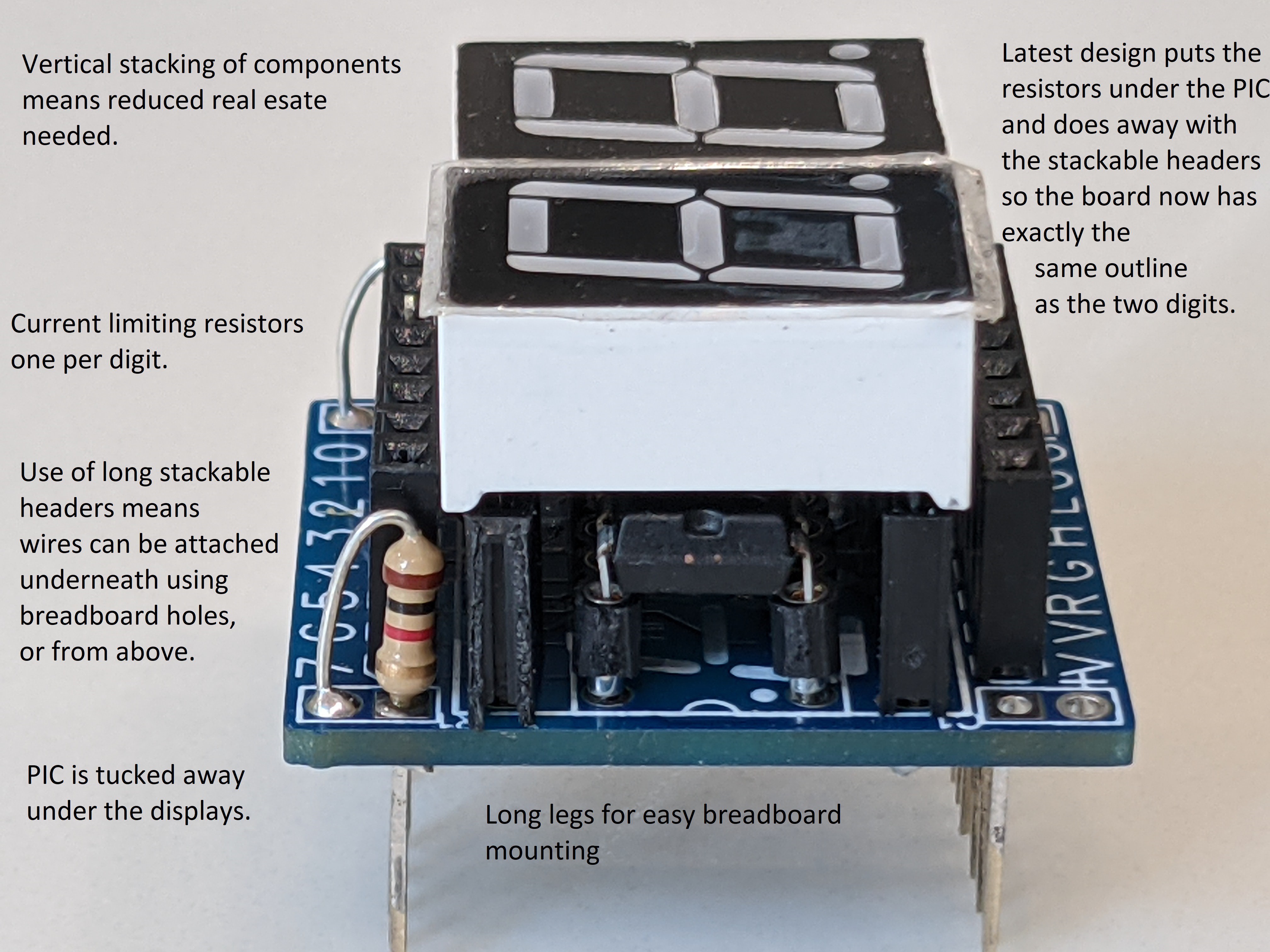
Like I said in the previous post this is still a bit too big for my liking.
Discussions
Become a Hackaday.io Member
Create an account to leave a comment. Already have an account? Log In.