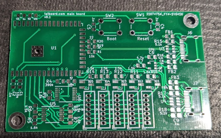
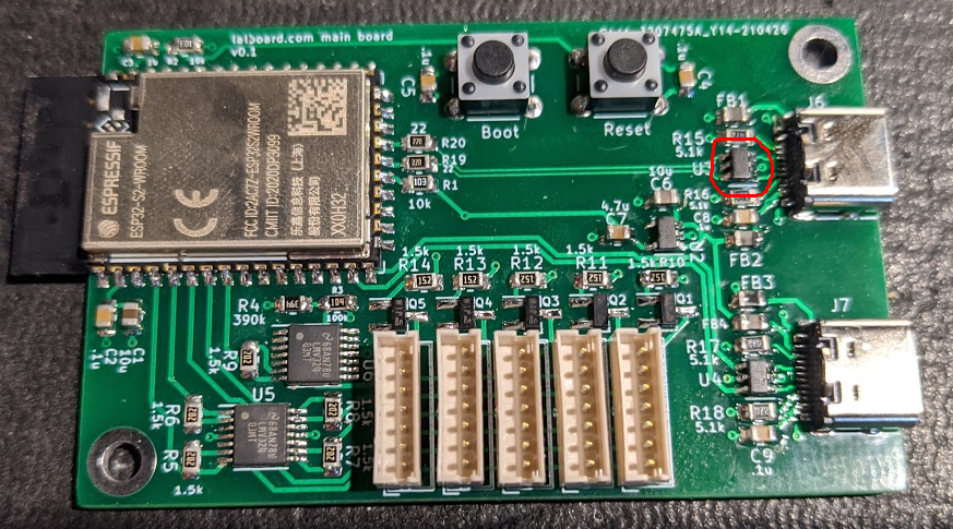
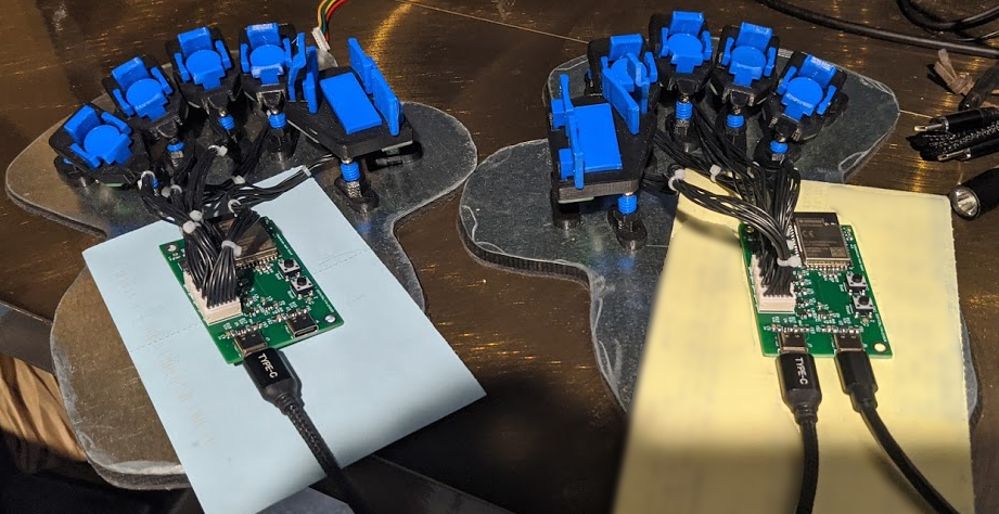
The central PCBs came in last week, and I got my first experience soldering fairly fine pitch SMD parts. I had just bought a stereo microscope recently, so I was able to put that to good use when soldering these.

The soldering wasn't actually nearly as hard as I was fearing. I think the USB-c connectors were probably the most difficult, but really not *too* bad. The ESP32-S2 module in particular was much easier than I was expecting.
After I got the first board soldered up, I ran into a couple of snags. At first, it wasn't enumerating as a USB device when booting into DFU mode. I used a little usb-power meter I had and confirmed that it was drawing more power when booted normally than when booted in DFU mode, so I was fairly sure the ESP module was booting and running.
After a fair bit of poking around, and desoldering various parts, I finally realized I had soldered the little TVS diode for the USB-C port backwards. I fixed that and was finally able to get it enumerating as a USB device and then flash it.

The next snag was that the clusters just weren't working. I wasn't getting any signal at all from the phototransistors. And again, after a fair bit of poking around, I finally realized I had wired the connectors backwards in the schematic and layout. At least, based on the way I had my existing JST-ZH cables wired. I had pin 1 on both sides as VCC, and pin 7 and ground. But of course, if the cable is wired normally, as mine are, the left pin (pin 1) on one side actually corresponds to the right pin (pin 7) on the other side.

Fortunately, this was an easy fix, since there was plenty of room on the board for the connectors to be placed the other way around. So I got those desoldered and flipped around, and was finally able to get the first keystrokes registered. Woo!
After that, there was a fair bit of futzing around with the firmware to get both sides working correctly and talking to one another. But I now have a working prototype, which I'm typing this log with :)

Now that I have a keyboard I can actually use, I've discovered a couple of minor problems that I'll need to address.
The first is that the central down keys have too much side-to-side wobble. You can feel them wobble as you place your fingers on them, and its a bit annoying. I did some quick tests, just placing some thin UHMW tape on either side of the post, and confirmed that that extra bit of thickness was enough to significantly reduce the amount of wobble. So I think I just need to tweak the size of the post and reprint them.
Another thing is that I noticed that I was commonly accidentally shifting the key after a shifted key press. I suspect the problem here might be that the thumb down key (the shift key) is registering as a press a bit too soon (and correspondingly, unpressing a bit too late). I want to see if I can figure out a way to measure the distance to when a press is registered, and compare the new design with the old design. I may need to tweak either the physical design of the thumb cluster a bit to compensate, or maybe just increase the drive current of the LED, so it requires the key be a bit further down before the phototransistor stops "seeing" enough light.
The other big thing that I'm working on is a better base. I'm thinking a plastic base (3d printed) with a void for a smaller steel sheet. The steel sheet will only be used for the clusters, but the handrest will be attached more firmly to the plastic base. I think this should have a few advantages over the current, somewhat ad-hoc, steel sheet solution.
- The handrest will be firmly attached and kept in position relative to the base plate. This allows the keyboard to be slid around by the handrest. With the handrests just attached magnetically to the steel sheet, if you try to slide the whole keyboard half by the handrest, the handrest just slides on the sheet, and becomes misaligned with the clusters.
- The steel sheet will be smaller, and will only have straight edges and convex corners, hopefully making it easier to manually cut out. e.g. by gluing a paper template to a sheet and using tin snips to cut it out.
- I'm thinking I can cover the edges of the steel sheet with an extra rim of plastic, making it look a bit neater, and avoiding having to clean up the cut edges of the sheet much.
 Ben Gruver
Discussions
Become a Hackaday.io Member
Create an account to leave a comment. Already have an account? Log In.
nice idea
Are you sure? yes | no