with the help of a MATLAB Simulink trial, I managed to animate My CAD assembly, to get a feel of how to manage the inverse kinematic model control on my embedded system.
here is the Block diagram of my Simulink:
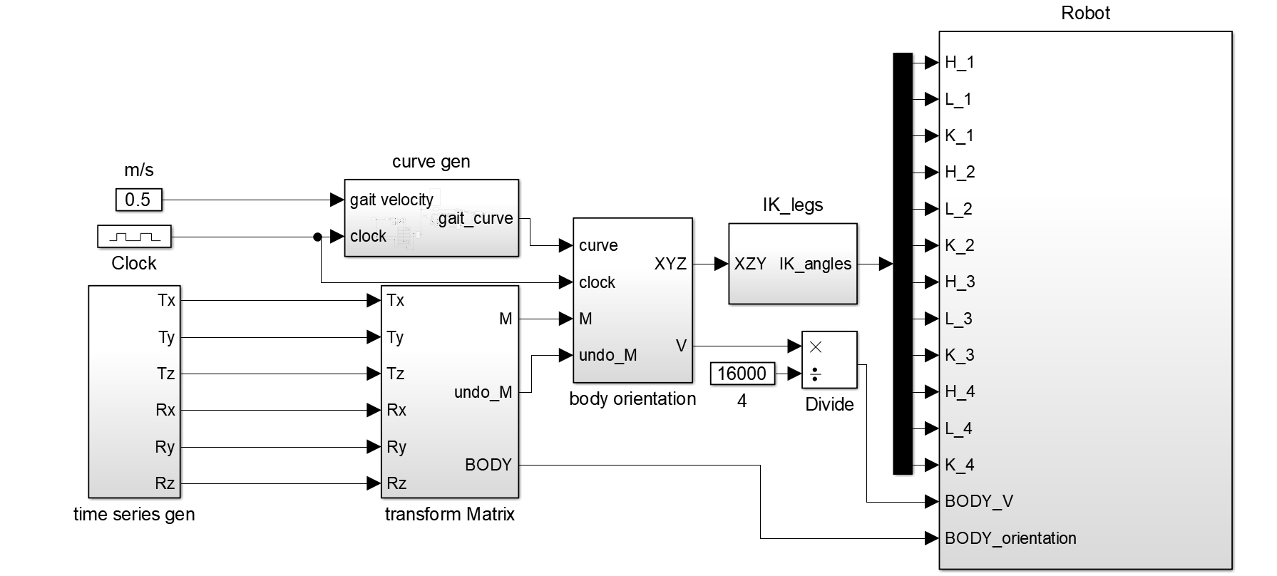
A Bezier curve is generated from 13 data points, to generate the path of the end effector as the robot walks, this curve widens as the velocity of the body increases. it is also rotated based on the "heading" angle, that dictates the walking direction of the robot.
this curve is then sent to the "body orientation" block, where, to handle the rotation of the local frames, to keep the end effector static to the world frame.
finally, the XYZ of each end effector is sent to the Inverse kinematic solver for the leg, that outputs the 3 necessary angles for each joint (H , L and K).
I have plans to make a DXF to timeseries converter, to make the robot move along the path drawn, but that is a future non-primary goal. I still have some control to do for the body velocity, as I don't have a convincing feedback of it.
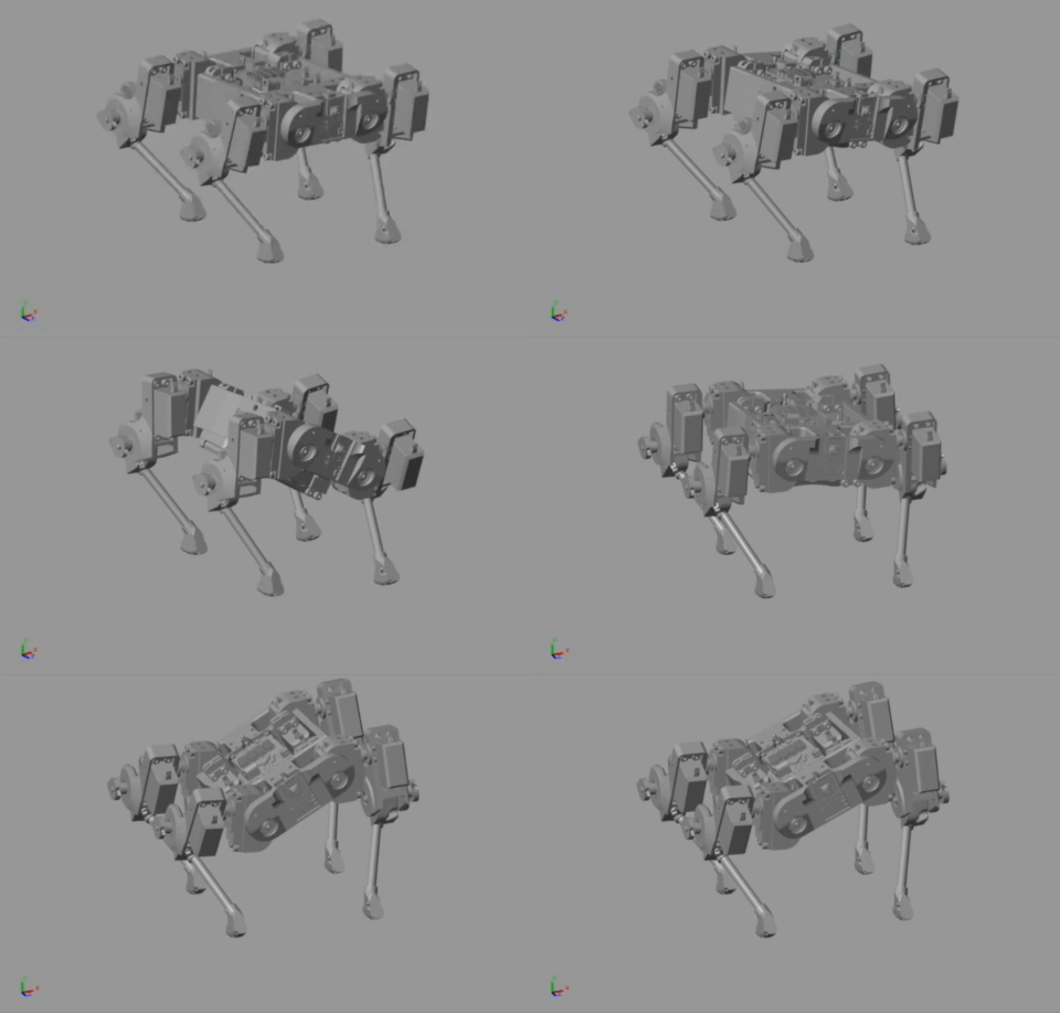
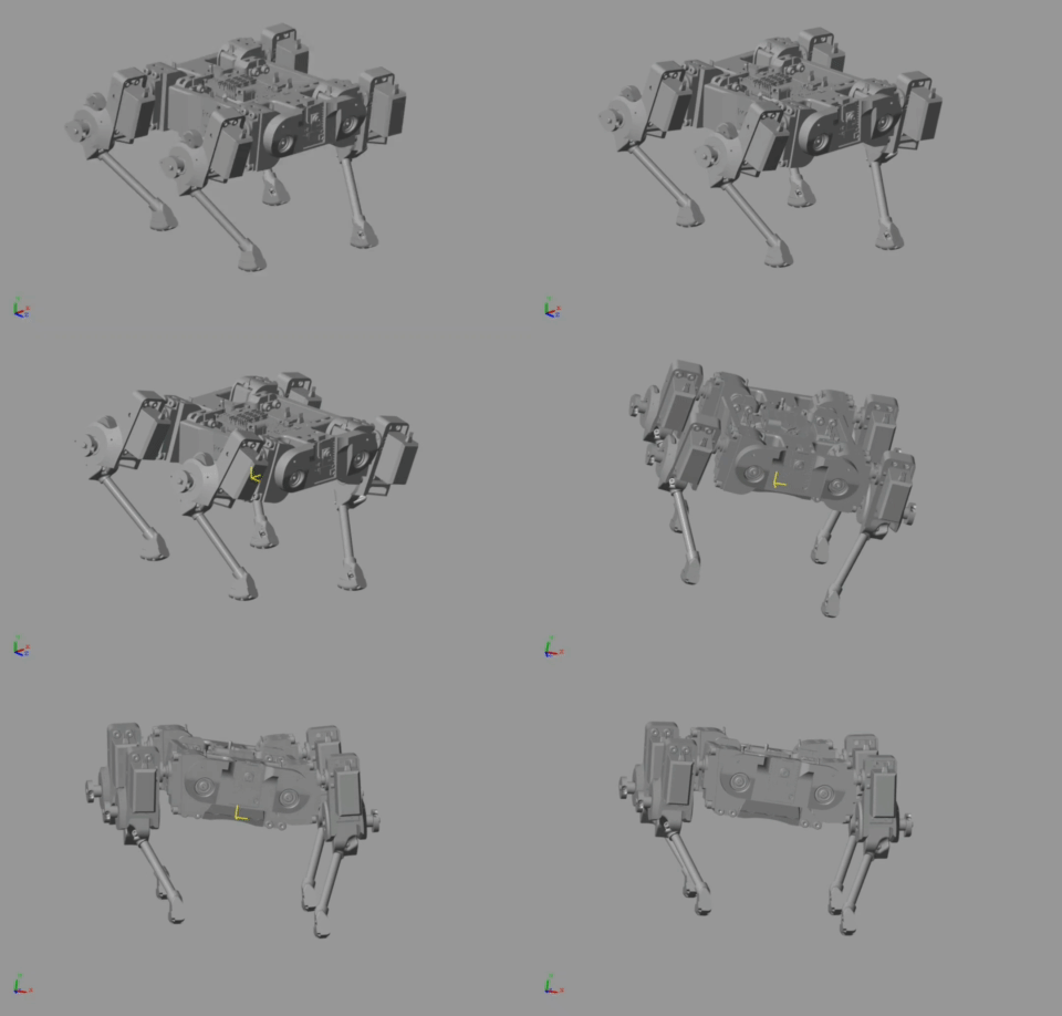
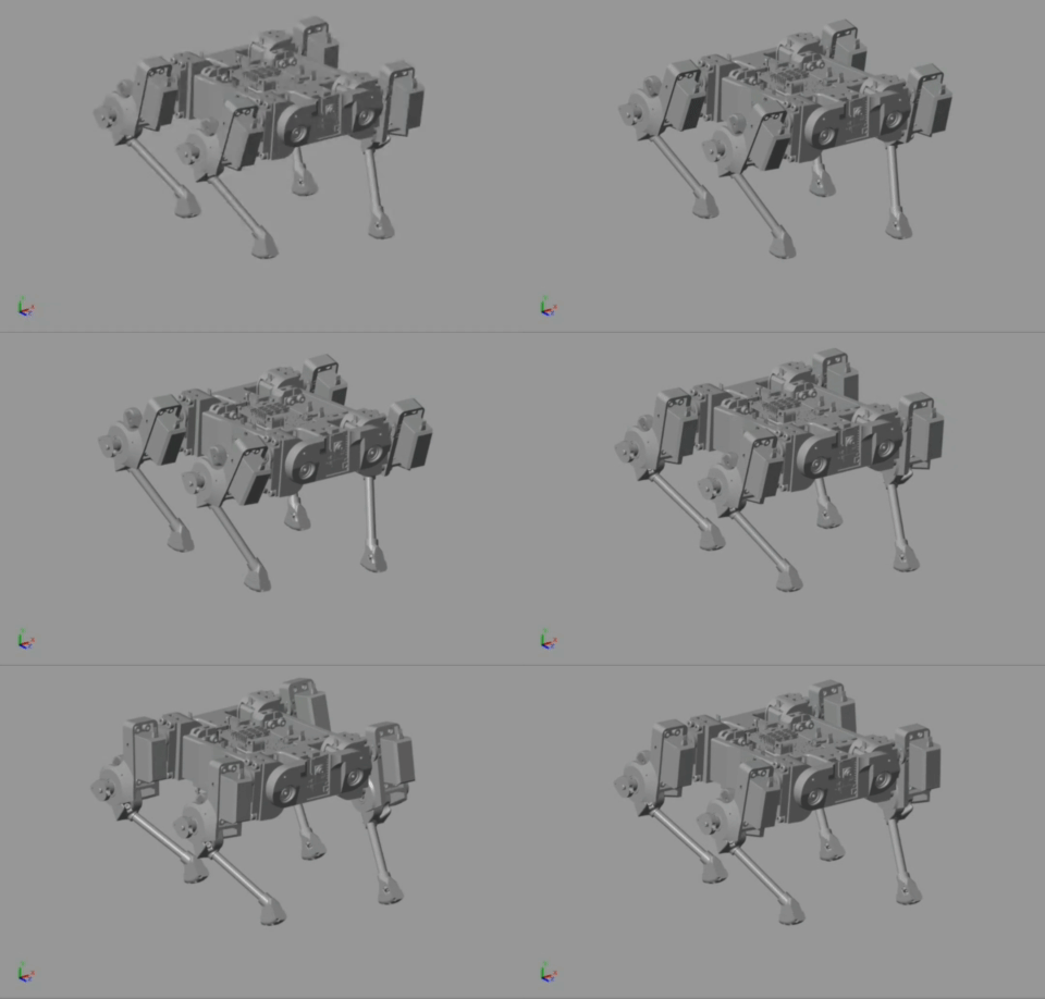
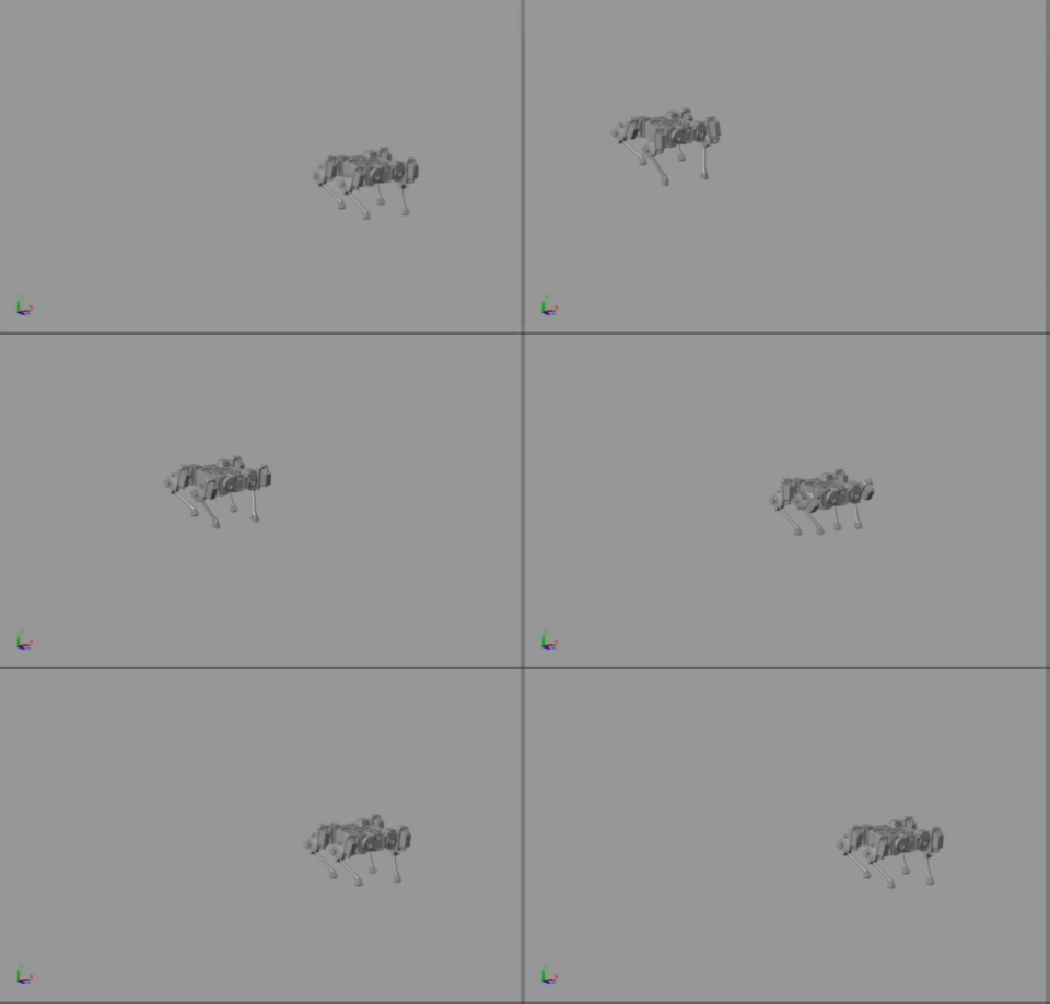
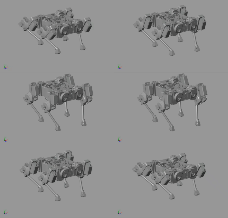
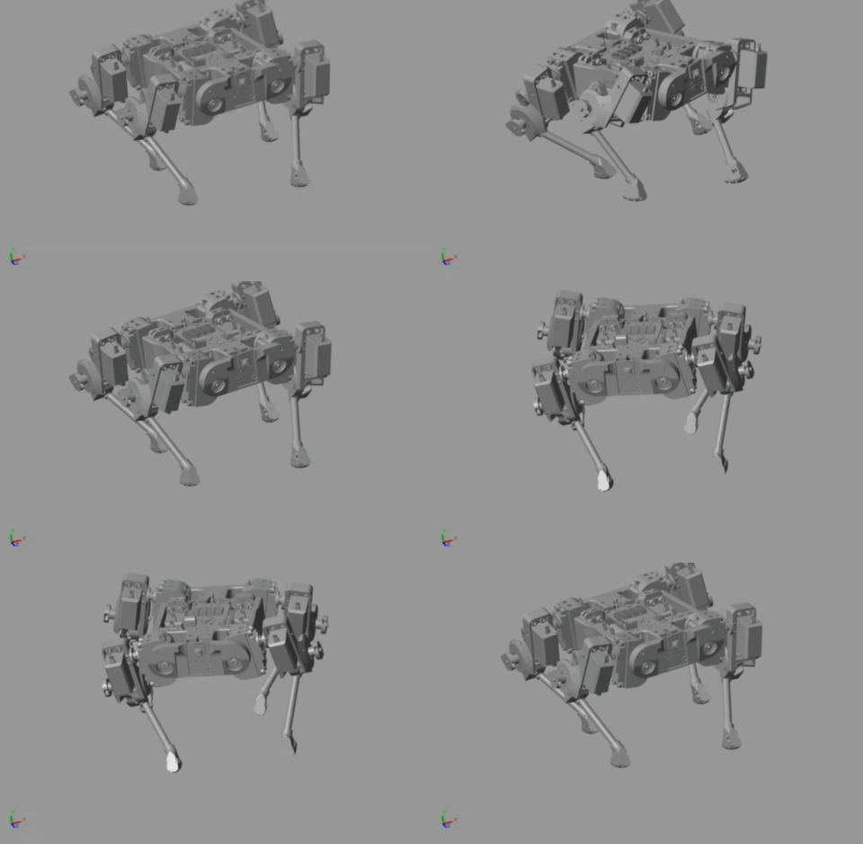
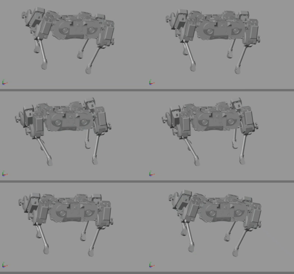
Here are some of the outputs I got with this block diagram:

 Wissam Tedros
Discussions
Become a Hackaday.io Member
Create an account to leave a comment. Already have an account? Log In.