 danjovic
it was necessary to shrink the pin change irq to fit within the timing necessary to attend the Z80.
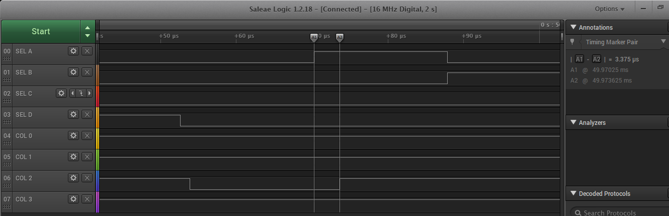
Doing the Math I should be spending 1us to output the code, counting the IRQ latency, but I have seen some figures of up to 3.25us which is barely enough.
It should be possible to increase this margin by changing the crystal to 20MHz, but I am testing with an arduino board (at 16MHz).
The code uses some tricks to save clock cycles like saving the registers r26 and r27 on general purpose I/O registers available in ATMega328, and using the __zero_reg__ to store the flags
volatile uint8_t zero = 0;
ISR (PCINT1_vect, ISR_NAKED) {
  asm volatile (                     // 7 instrucoes de latencia até aqui
    "in __zero_reg__,__SREG__ \n\t"  // 1 Salva registrador de Status
    "out %[_GPIOR1],r26\n\t"         // 1 salva registro em 1 ciclo
    "out %[_GPIOR2],r27\n\t"         // 1 salva registro em 1 ciclo

    "ldi r27,hi8(Keymap)\n\t"        // 1 Ponteiro X = endereço de Keymap
    "in r26,%[_PINC] \n\t"           // 1
    "subi r26, lo8(-(Keymap)) \n\t"  // 1
    "ld 26,X \n\t"                   // 2 lê coluna correspondente do mapa de teclas
    "out %[_DDRD] ,r26 \n\t"         // 1 escreve na porta B da PPI
                                     // até aqui 16 instruções (1us @16Mhz)
    "in r26, %[_GPIOR1] \n\t"
    "in r27, %[_GPIOR2] \n\t"

    "sbi %[_PCIFR],1 \n\t"           // reset interrupt bit

    "out __SREG__,__zero_reg__ \n\t" // restaura registrador de Status
    "lds __zero_reg__, zero \n\t"
    "reti \n\t"

    ::[_PINC] "I" (_SFR_IO_ADDR(PINC)  ),
    [_DDRD]   "I" (_SFR_IO_ADDR(DDRD)  ),
    [_PORTB]  "I" (_SFR_IO_ADDR(PORTB) ),
    [_GPIOR1] "I" (_SFR_IO_ADDR(GPIOR1)),
    [_GPIOR2] "I" (_SFR_IO_ADDR(GPIOR2)),
    [_PCIFR]  "I" (_SFR_IO_ADDR(PCIFR) )
    );

}
Discussions
Become a Hackaday.io Member
Create an account to leave a comment. Already have an account? Log In.