 Joel Kozikowski
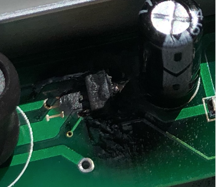
For future reference, the GPIO pins on the Raspberry Pi supports a maximum of about 50 mA of current through the GPIO pins. As I was laying out the rev 2 PiHat board, I mistakenly routed the GND trace of the UV lamp thru a conveniently nearby GND pin on the Raspberry Pi (vs. making a trace directly to the primary ground trace). Big mistake on my part. A bad solder joint actually made the UV lamp work in this configuration for a short period, but once I fixed the joint, I managed to damage the Pi, which in turn sent too much current through the LED control pin of the UV lamp chip, which in turn smoked it in a spectacular fashion! Fortunately I had a spare Pi and a spare Sparkmaker UV lamp (my China shipment finally arrived), which allowed me to test Rev 2.1 of the PiHat.
Lesson learned: The Rat's Nest lines of your EDA tool may pick the nearest connection point, but it may not be the one you need. :)
The rev 2.1 board fixes and Gerber files have been uploaded to GitHub.
Discussions
Become a Hackaday.io Member
Create an account to leave a comment. Already have an account? Log In.