 zpekic
One very interesting feature of V99X8 VDPs is the "color bus". These 8 pins usually carry the color (or color index) of the pixel being drawn, but can be also used as inputs for external video signals. These modes are described on pg. 109 of the "technical data book".
I neglected to look deeper at the color bus, but fellow hackaday user tomcircuit gave me a great idea how to use it. I already had the whole software + hardware + test rig 95% ready, here are the changes I did to use it.
1. Atrocious hardware hack
This is something that should never be done, but in this case it was the quick and lazy way - I soldered 4 wires directly to bits 3...0 of the color bus to tap into those signals (pins 16, 17, 18, 19).

this creates a 4-bit digital pixel signal. The original project had 3 digital lines (R, G, B) so I had to add 1.
VDP_I_DIG <= PMOD(4); -- INPUT! -- Bit3 from color bus
2. Extending the FPGA pixel width from 3 to 4 bits
The "DLCLK" signal is not used in this project, instead I recreated it in the FPGA using CPUCLK, and this internal clock can be tweaked using a delay line configurable by switches on the FPGA board. This allows timing "fine tuning":
i_delayed <= i_line(to_integer(unsigned(switch(7 downto 6) & '1'))); -- use "red" switches
r_delayed <= r_line(to_integer(unsigned(switch(7 downto 6) & '1')));
g_delayed <= g_line(to_integer(unsigned(switch(5 downto 4) & '1')));
b_delayed <= b_line(to_integer(unsigned(switch(3 downto 2) & '1')));
The new "i" line has to be brought to the sampler to be captured. Luckily the MSB of the "color nibble" was free.
| Mode | Dual port RAM byte structure | Notes |
| RGB | 0RGB0RGB | MSB is hard coded to 0 |
| Color bus | c3c2c1c0c3c2c1c0 | c3 = "i" signal c2 = pin 17 drives "R" input c1 = pin 18 drives "G" input c0 = pin 19 drives "B" input |
The net result is very clean 2 16-color pixels per byte in FPGA dual port video RAM:
on_sample_pulse: process(sample_pulse, i, r, g, b, sample)
begin
if (rising_edge(sample_pulse)) then
sample <= sample(3 downto 0) & i & r & g & b;
end if;
end process;
3. Color palette update
With 3 bits per pixel directly mapped to R, G, B there is not much to be done in terms of color palette: 000 will logically map to "black" and 111 to "white" etc.
With 4 bits (or more, up to 8), the color bus can be interpreted to carry the "index" and an external memory (for example 256 * 24 bits) can define the exact color meaning of each index. This is of course easy to do in FPGA so here the mapping I implemented:
-- standard TMS9918 16-color palette (http://www.cs.columbia.edu/~sedwards/papers/TMS9918.pdf page 26)
signal video_color: color_lookup := (
    color_transparent,    -- VGA does not support is, so "black"
    color_black,
    color_medgreen,
    color_ltgreen,

    color_dkblue,
    color_ltblue,
    color_dkred,
    color_cyan,

    color_medred,
    color_ltred,
    color_dkyellow,
    color_ltyellow,

    color_dkgreen,
    color_magenta,
    color_gray,
    color_white
    );
With the palette defined above, the VDP color can be described as "any 16 colors out of 256", that's because the width of the palette register is 8 bits, defined as:
RRRGGGBB
Here is the definition of the colors used in the palette:
constant color_transparent:				std_logic_vector(7 downto 0):= "00000000";
constant color_medgreen: 					std_logic_vector(7 downto 0):= "00010000";
constant color_dkgreen:						std_logic_vector(7 downto 0):= "00001000";
constant color_dkblue:						std_logic_vector(7 downto 0):= "00000010";
constant color_medred:						std_logic_vector(7 downto 0):= "01100000";
constant color_dkred:						std_logic_vector(7 downto 0):= "01000000";
constant color_ltcyan:						std_logic_vector(7 downto 0):= "00001110";
constant color_dkyellow:					std_logic_vector(7 downto 0):= "10010000";
constant color_magenta:						std_logic_vector(7 downto 0):= "01100010";

constant color_black:			std_logic_vector(7 downto 0):= "00000000";
constant color_blue,	color_ltblue:	std_logic_vector(7 downto 0):= "00000011";
constant color_green,	color_ltgreen:	std_logic_vector(7 downto 0):= "00011100";
constant color_cyan:			std_logic_vector(7 downto 0):= "00011111";
constant color_red,	color_ltred:	std_logic_vector(7 downto 0):= "11100000";
constant color_purple:			std_logic_vector(7 downto 0):= "11100011";
constant color_yellow,	color_ltyellow: std_logic_vector(7 downto 0):= "11111100";
constant color_white:			std_logic_vector(7 downto 0):= "11111111";
constant color_ltgray:			std_logic_vector(7 downto 0):= "01101110";
constant color_dkgray,  color_gray:	std_logic_vector(7 downto 0):= "10010010";
With the modified Propeller test code (see below) this gives following colors (yellowish small bars on the bottom is my zombie sprite bug in Propeller code :-) ):
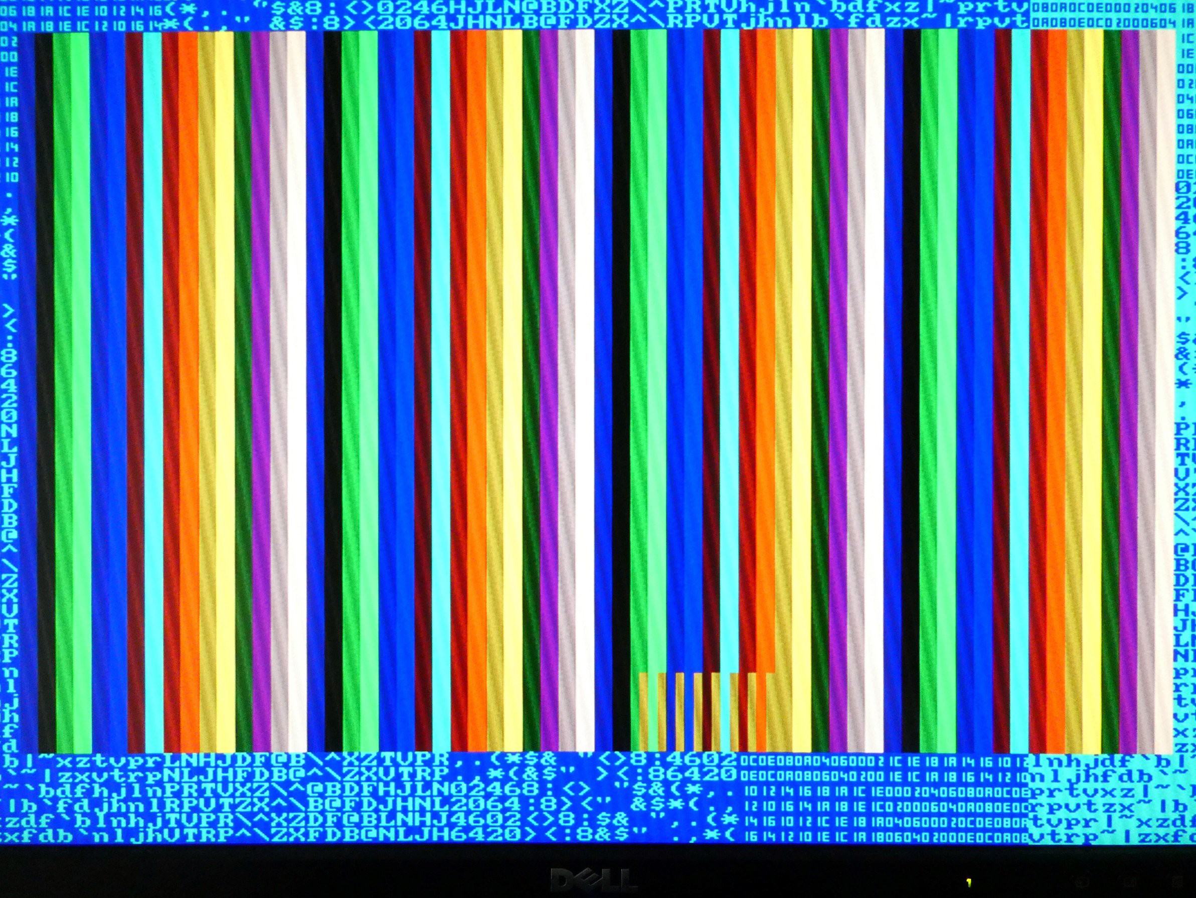
Note that "color 0" ("transparent") magically really works - the VDP simply decides to let the background color come through (first "dark blue") vertical bar in the VDP display window.
4. Test code update
Just a minimal change was needed, to see the 16 colors in action:
PRI _colorfulBlocks(color) |x, y, c
  c := 0
  repeat x from 0 to vdp.GraphicsHPixelCount - 1
    repeat y from 0 to vdp.GraphicsVPixelCount - 1
      if (color == vdp#TRANSPARENT)
        vdp.DrawPixel(x, y, x ^ y)
      else
        'vdp.DrawPixel(x, y, ColorPalette8[x & 7])
        vdp.DrawPixel(x, y, x & 15)
        c++
  vdp.WaitASecond
The x coordinate (which goes from 0 to 63) is used to set the color 0 ... 15.
No other code changes were done. But the results are much better than with the primitive 1-bit RGB A/D converter:
- 16 colors instead of 8
- no color bleeding or wrongly sampled pics
Here are some examples of demo screens using the color bus (lame pics of the screen, the actual quality is much better):
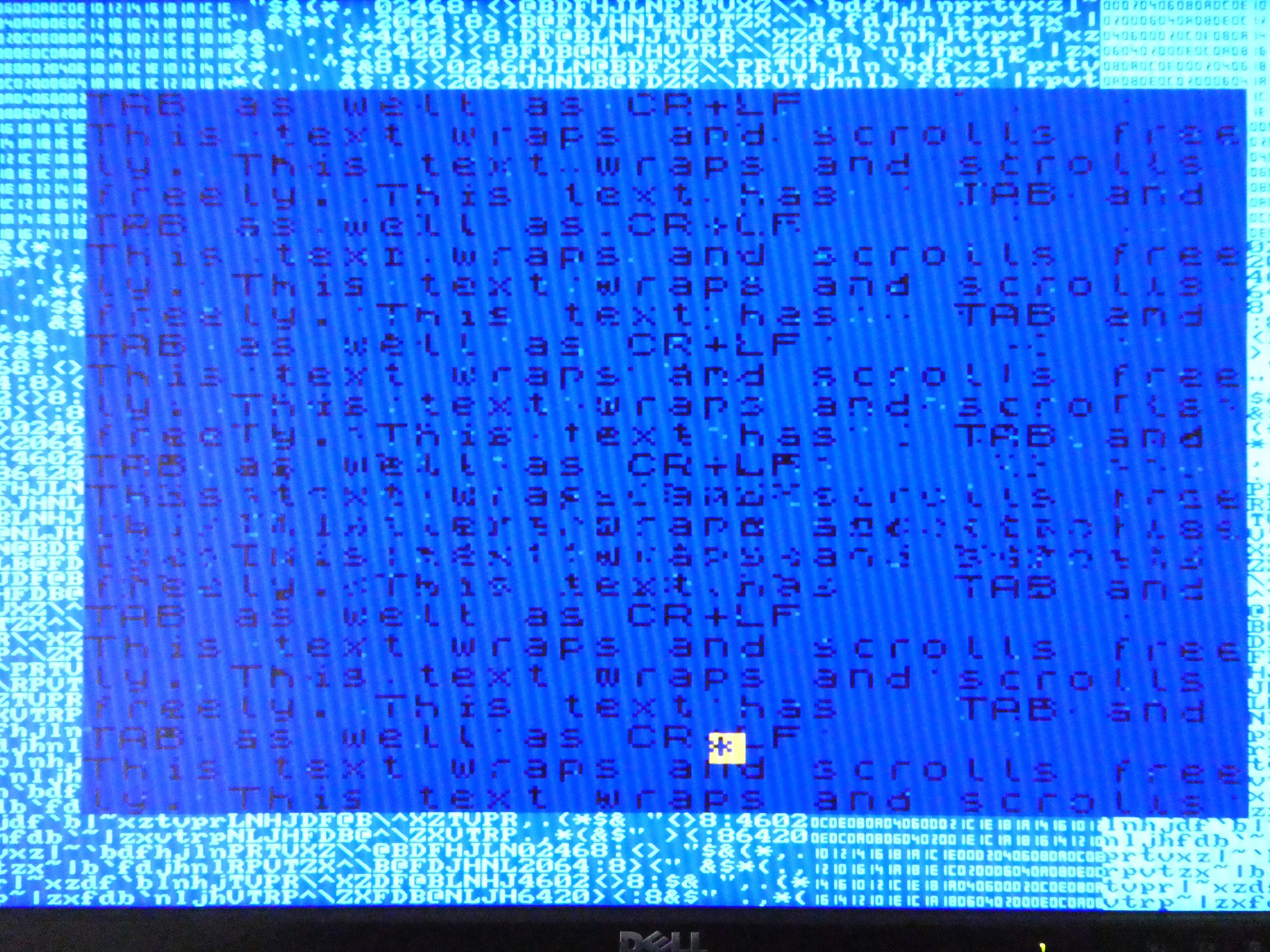
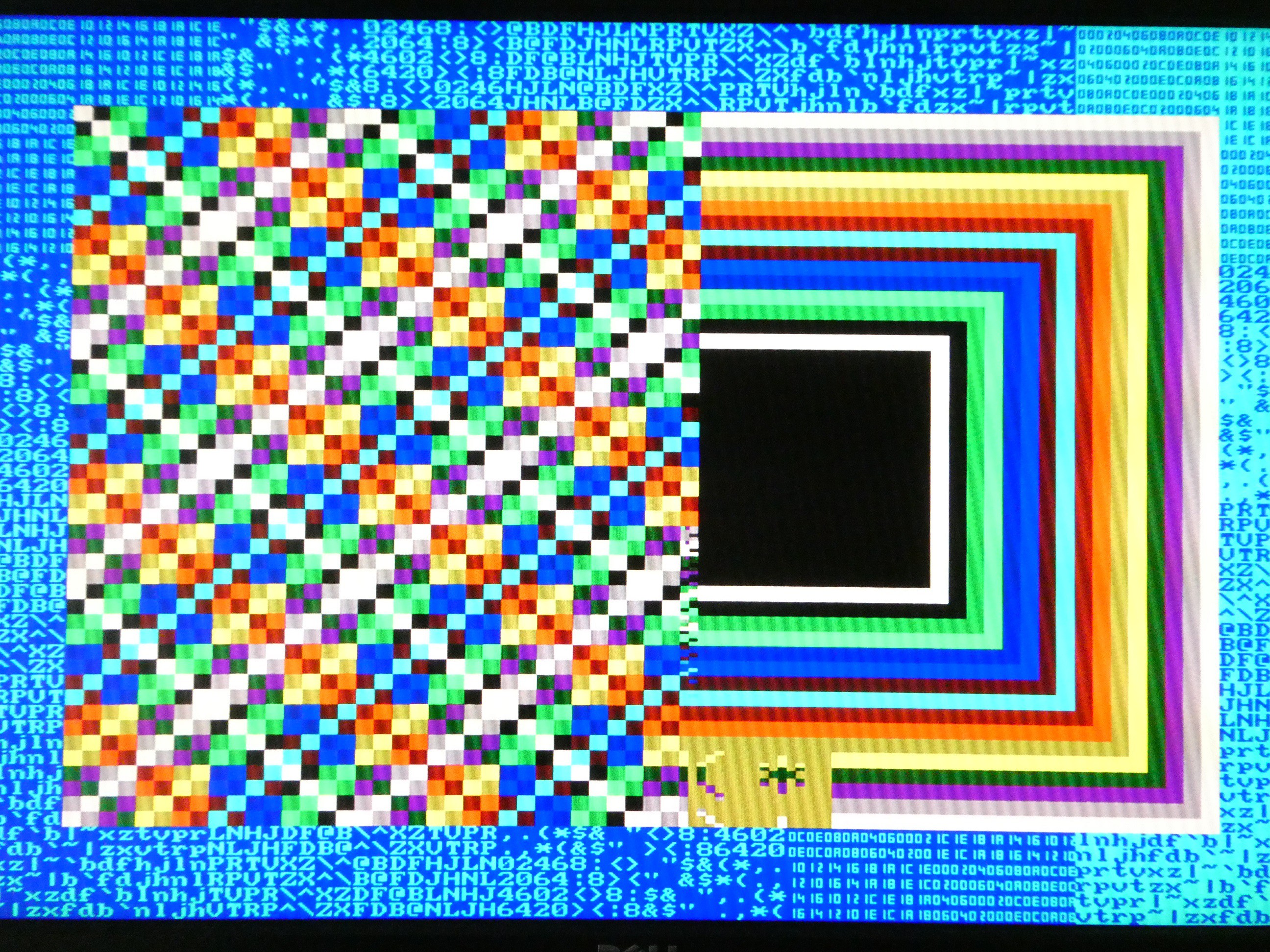
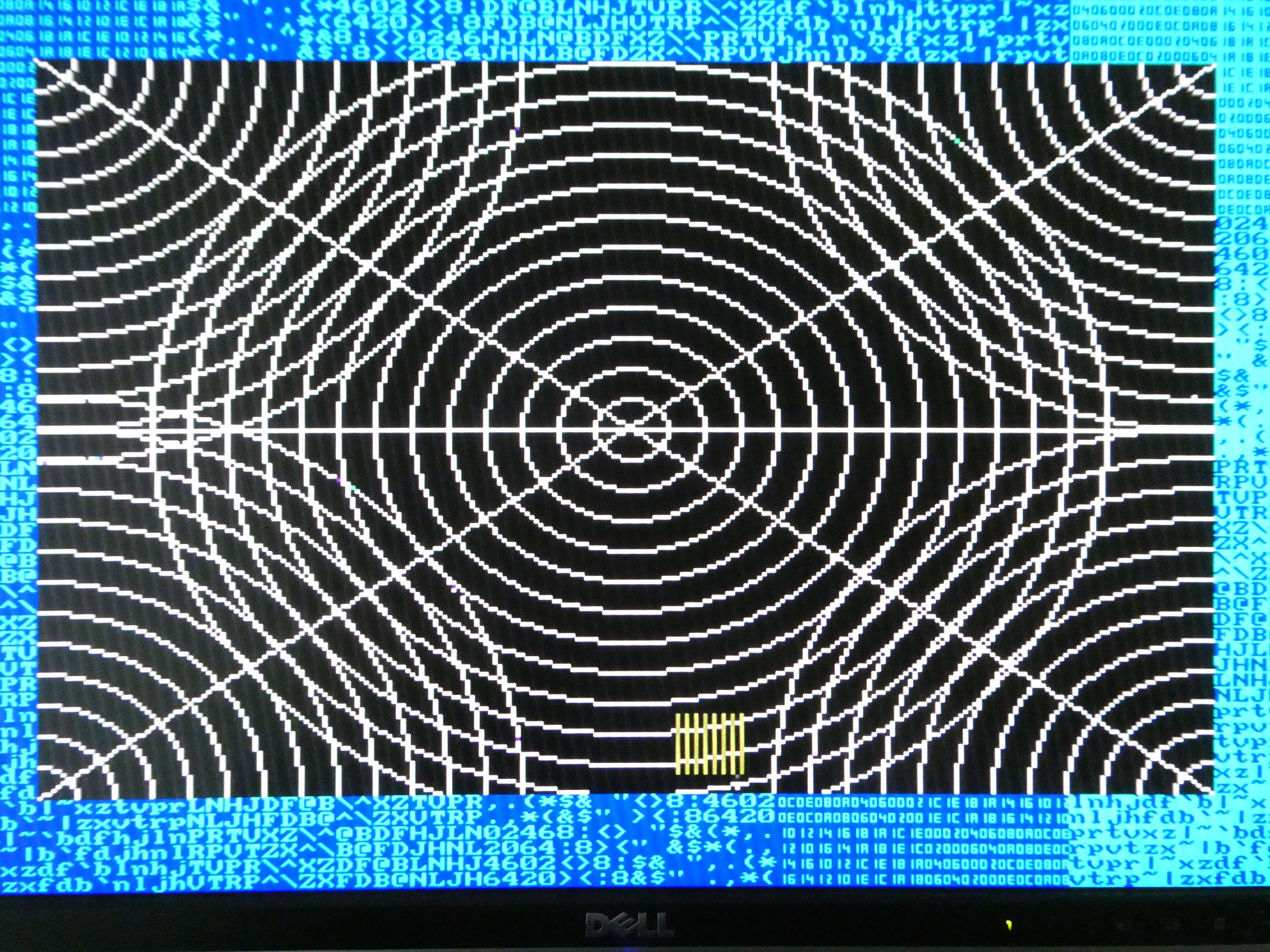
I have bugs with sprite patterns, but it can be observed that in case of scroll the VGA output can display the "picture in flux" - remember that sampler runs at VDP sync, and VGA at its own sync and they are completely async to each other.

5. Conclusion
Sampling the analog RBG outputs of V99X8 VDPs is possible and can lead to acceptable VGA picture, it requires higher quality A/D converters, PCBs and connections.
Sampling the color bus on the other hand leads to high-quality VGA sampling even with most basic hardware, essentially just direct wiring from VDP to FPGA.
I leave to some hardware wizard to create V99X8-based VGA board. In its simplest form, such board could contain only:
- V99X8
- FPGA (depending on the resources can contain VDP "dynamic" RAM, VGA "dual port" RAM, and the sampler / VGA controller described here)
- D/A VGA output circuit and connector
The board could be made to accept various "adapters" such as for RC2014, rosco_m68k, or even directly TMS9918 socket pinout (VGA for TI-99/4A!)
Discussions
Become a Hackaday.io Member
Create an account to leave a comment. Already have an account? Log In.