 Florian Wilhelm Dirnberger

0. Outline
A probe (either resistive or capacitive type) delivers an analog value (i. e. voltage) representing the soil moisture, a Raspberry Pi Pico converts the sensor signal into a 16-bit (actually a 12-bit) digital value. This value is then mapped to 0% - 99% soil moisture by means of a simple MicroPython algorithm (linearity assumed).
Other sorts of sensors can be connected in lieu of a moisture sensor, as done in this project (e.g. HIH 4020, relative humidity).
I also designed IoT versions of these devices (not using Pico W, but Pico+ESP8266), without any display at all.
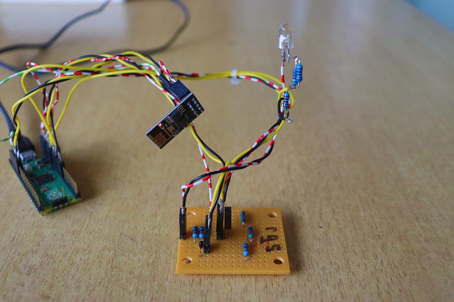
1. IoT Prototype w/ capacitive probe
2. Soil moisture sensors
Either one of the following sensor types can be used for the moisture measurement (sensor output here connected to ADC0/GP26):
- Capacitive type sensor HW-390 (also referred to as v2.0)
- Resistive type sensor ME110
An initialization routine can identify the connected sensor type (see MicroPython code in my github repo).
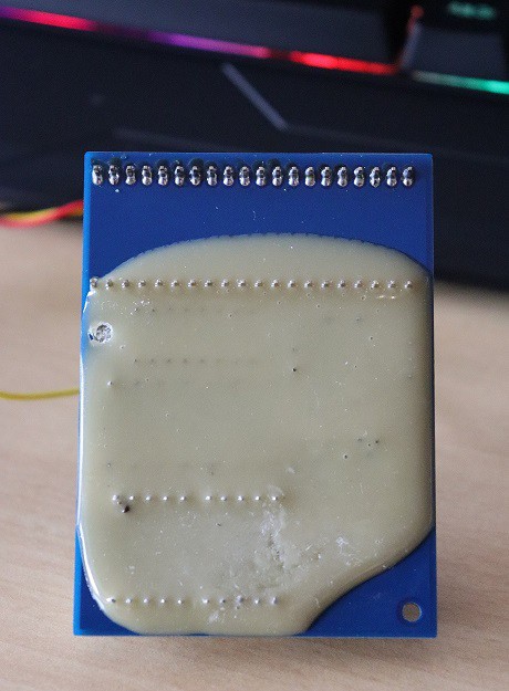
The capacitive probe is more expensive, but certainly better because that is the durable sensor that won't corrode - the anode metal of the ME110 will have vanished after a few hours of sticking in the soil (see photo below).
Both sensors show temperature dependency to some degree (roughly Δ 1% per Δ 1°K).

3. Humidity sensor
Prototypes are also used for relative humidity readings with HIH 4020 sensor (only as IoT version essentially). Parts of the already created algorithm had to be enhanced and modified for this obviously (see links to my github repo).
A basic output in a web browser (as to the ambient light sensor, see project log):
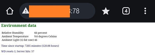
Note: for the IoT-server there are a few ad-hoc robustness measures in place, such as activating the HW watchdog and not using standard http port 80. Security is not implemented (SSL/TLS), so I would advice against making such a device accessible to the wider world.
4. 7-Segment-Displays
I am using three different variants of common cathode 7-Segment-Displays which have slightly different electrical characteristics (they're identical in regards to geometry):
- SC56-11GWA: green
- SC56-11EWA: red
- SC56-11YWA: yellow (those I personally like the most)
This means more precisely that red LEDs have the lowest threshold voltage, green LEDS the highest (keeping in mind the statistical dispersion with individual LEDs).
Notes:
1. Though the ADC of the Pico has some problems (see RP2040 documentation), it is surely good enough for this kind of application.
2. Driving the segments (i. e. LEDs) of the 7-Segment-Displays directly is probably not good an idea since one individual Pico GPIO can deliver 12 mA at most, and it is unclear what the Pico's supply current upper limit is (on all its GPIOs combined). The documentation states something about 50mA, what is clearly not enough to drive a lot of segments at once.
3. The CD4511BE driver has a V_BE voltage drop (see data sheet), and so have the multiplexing transistors. That leads to a diminished voltage budget for the segment LEDs and the resistors R1-R7, respectively, what must be taken into account when calculating the resistor values.
5. Summary
During the course of this project, four arrangements have been considered, built and tested.
Soil moisture:
1. IoT
2. 7-Segment-Displays
Air humidity:
3. IoT
4. 7-Segment-Displays
A code example in Micropython is given for arrangement 2, a code example in C is given for arrangement 3.

 mircemk
 PKvirus
 Marcrbarker
 Ai-Thinker