 Thorsten Jaeger
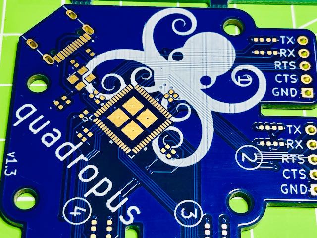 PCBs arrived and they are simply beautiful. It's not many components, so it takes 20 minutes to mount and 5 to reflow.
Using SIlabs STUDIO to give it a name and identity (quadropus as you can guess) and set some GPIO ports to act as TX/RX activity LED.
Works like a champ.
I added some colored Pin headers to each of the UART Sections 1-4 and used same colored cables - so even working with multiple serial hookups you keep track easily which TX goes where :)

What is RX and what is TX ?
A classic question. Here is the definition for quadropus:
TX Label (from quadropus or "usb host" view) is when Data is TX (transmitted) to the attached serial Device FROM the USB-Host - represented by Amber LED
RX Label (from quadropus or "usb host" view) is when Data is RX (received) from the attached serial Device INTO the USB-Host - represented by Green LED
Discussions
Become a Hackaday.io Member
Create an account to leave a comment. Already have an account? Log In.