 Dominik Meffert
My next goal is to measure the speed of the ink stream by using two sensors and counting the time the droplets need to travel from sensor to sensor.
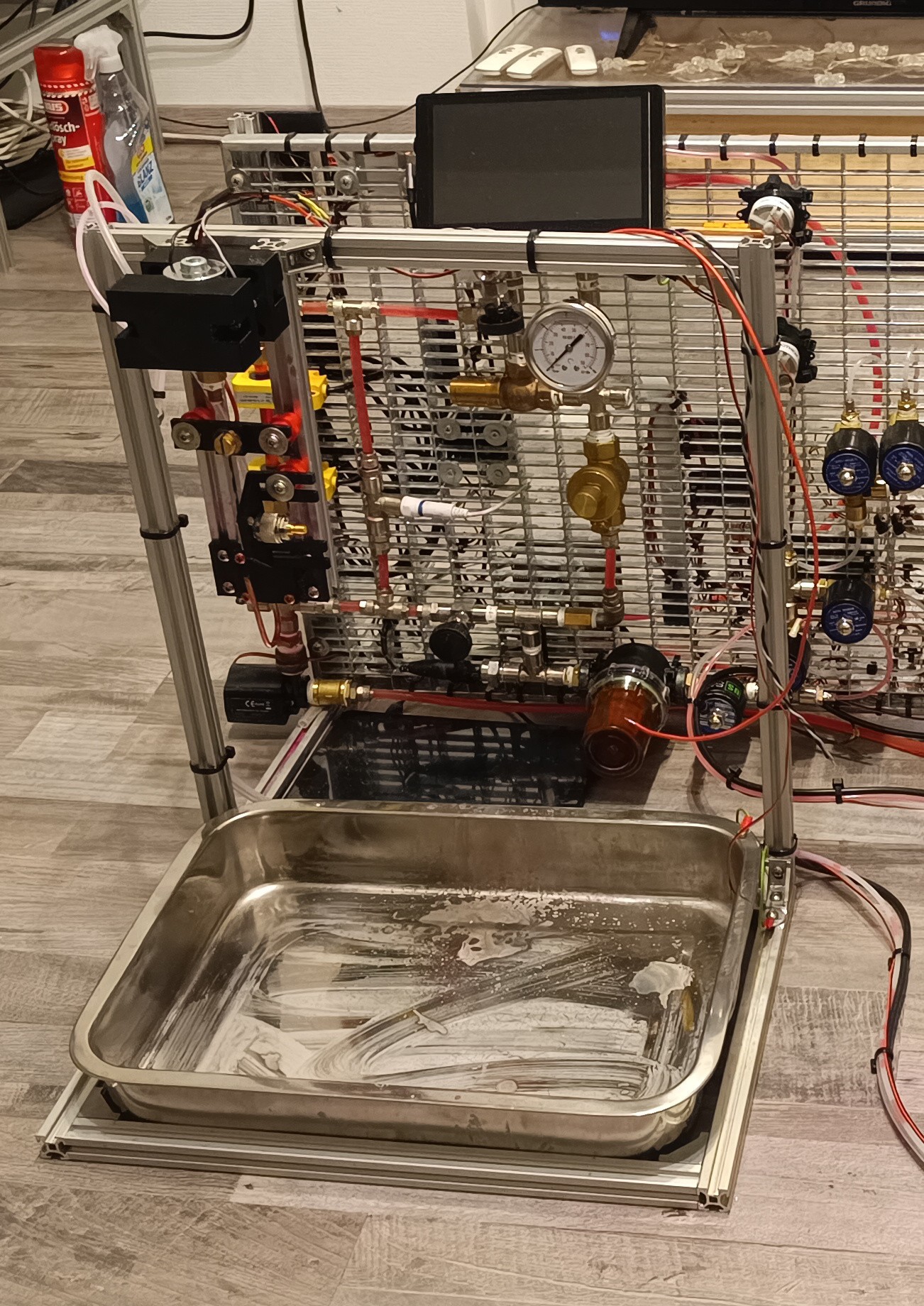
To make work on the electronics easier, I built a new printhead test stand with a drip tray for catching ink drops that miss the gutter.
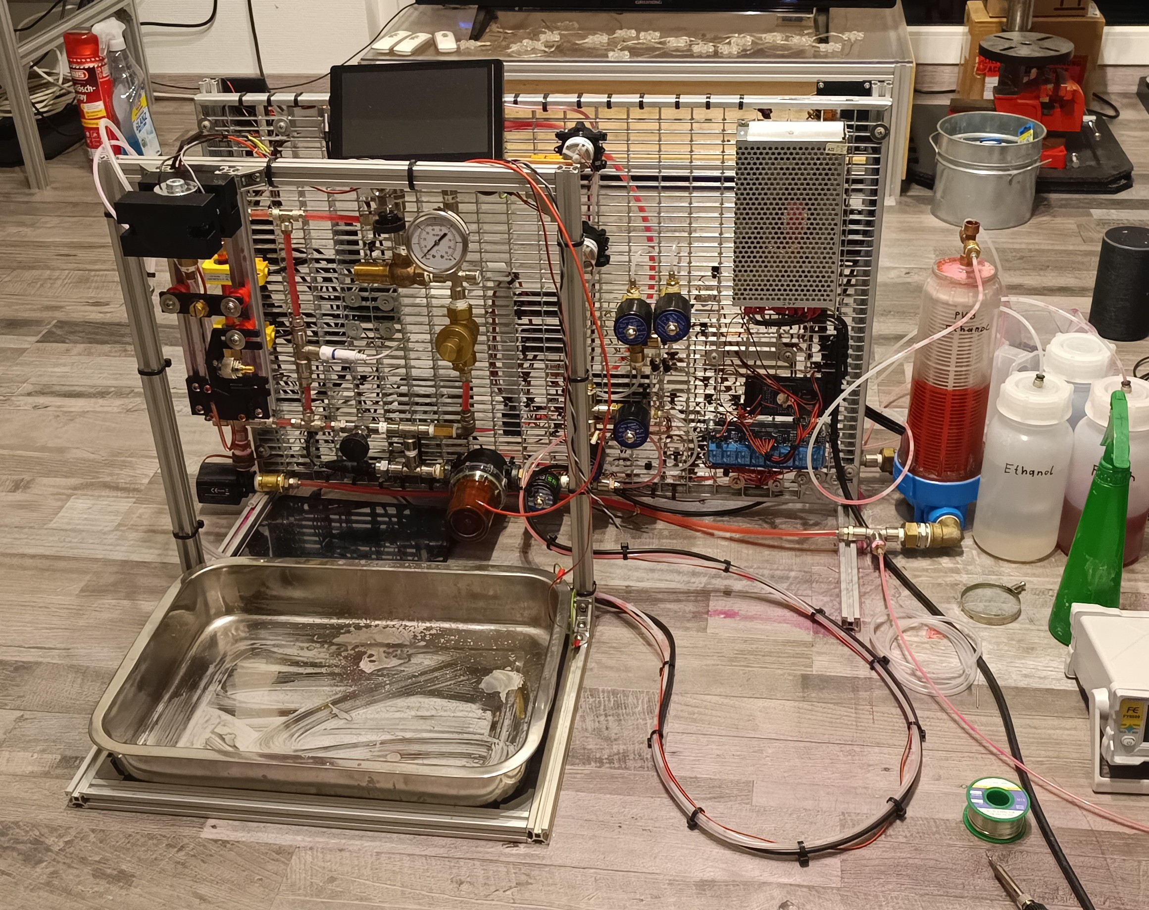
After everything was in place, I tried building an amplifier for measuring the small charge that would be applied to the droplets by a Time-of-flight test signal.


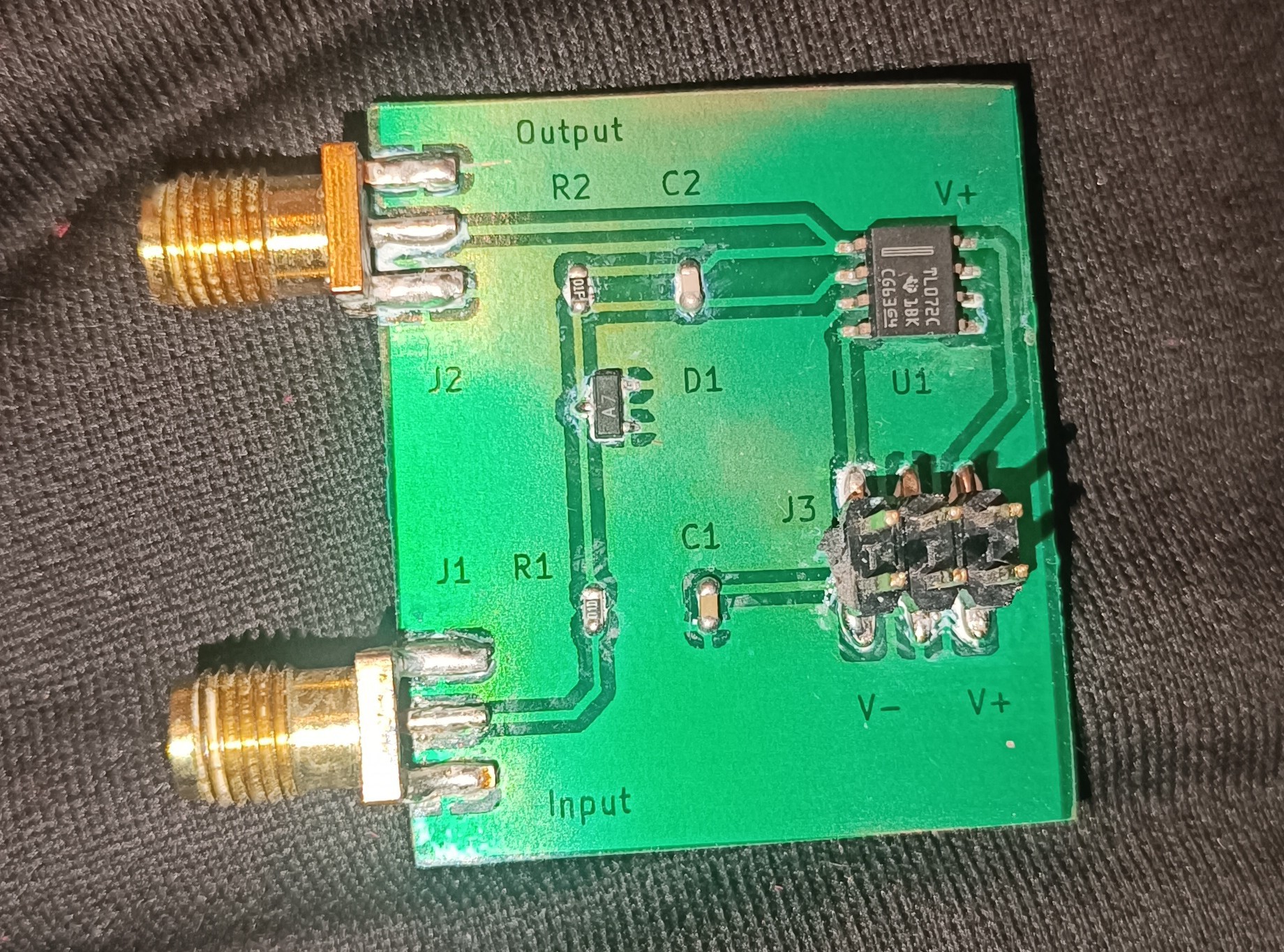
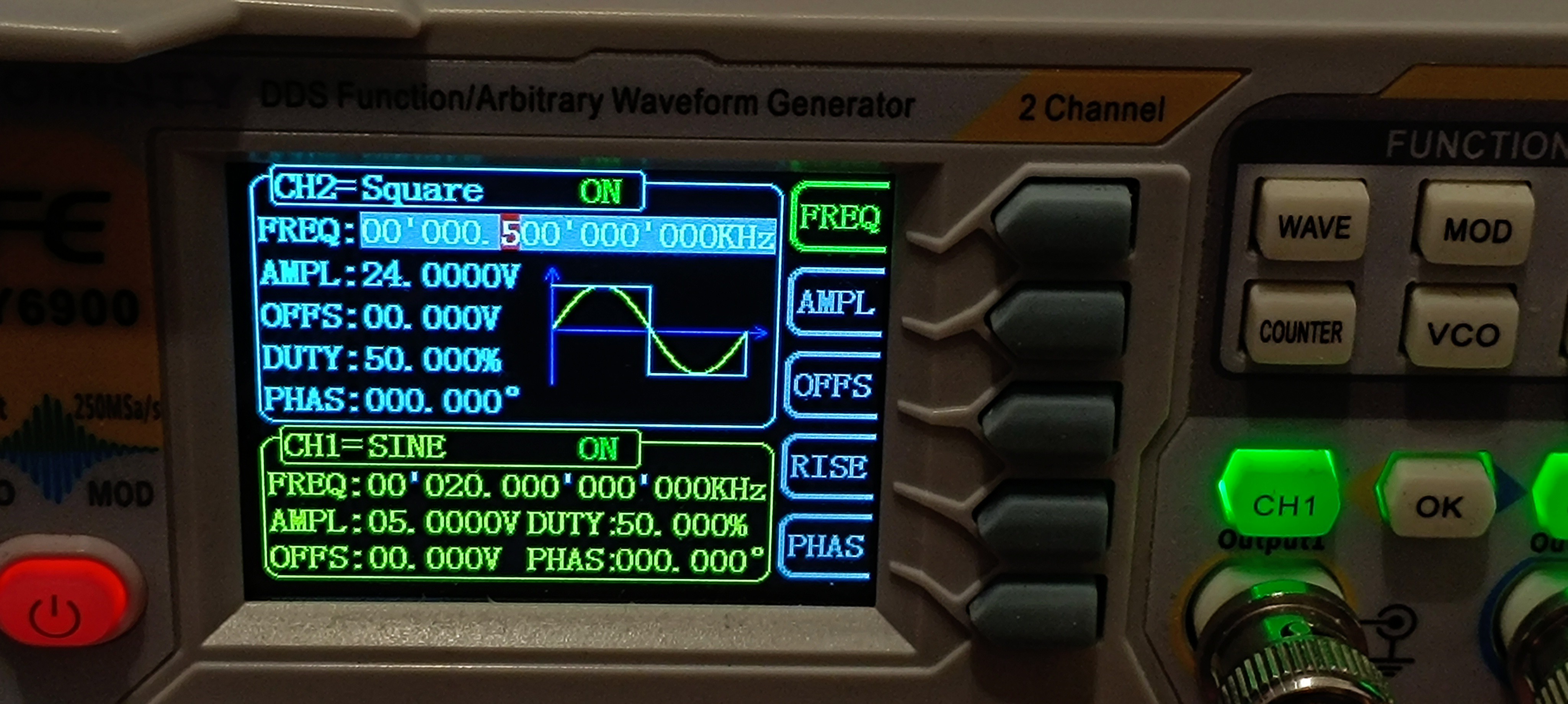
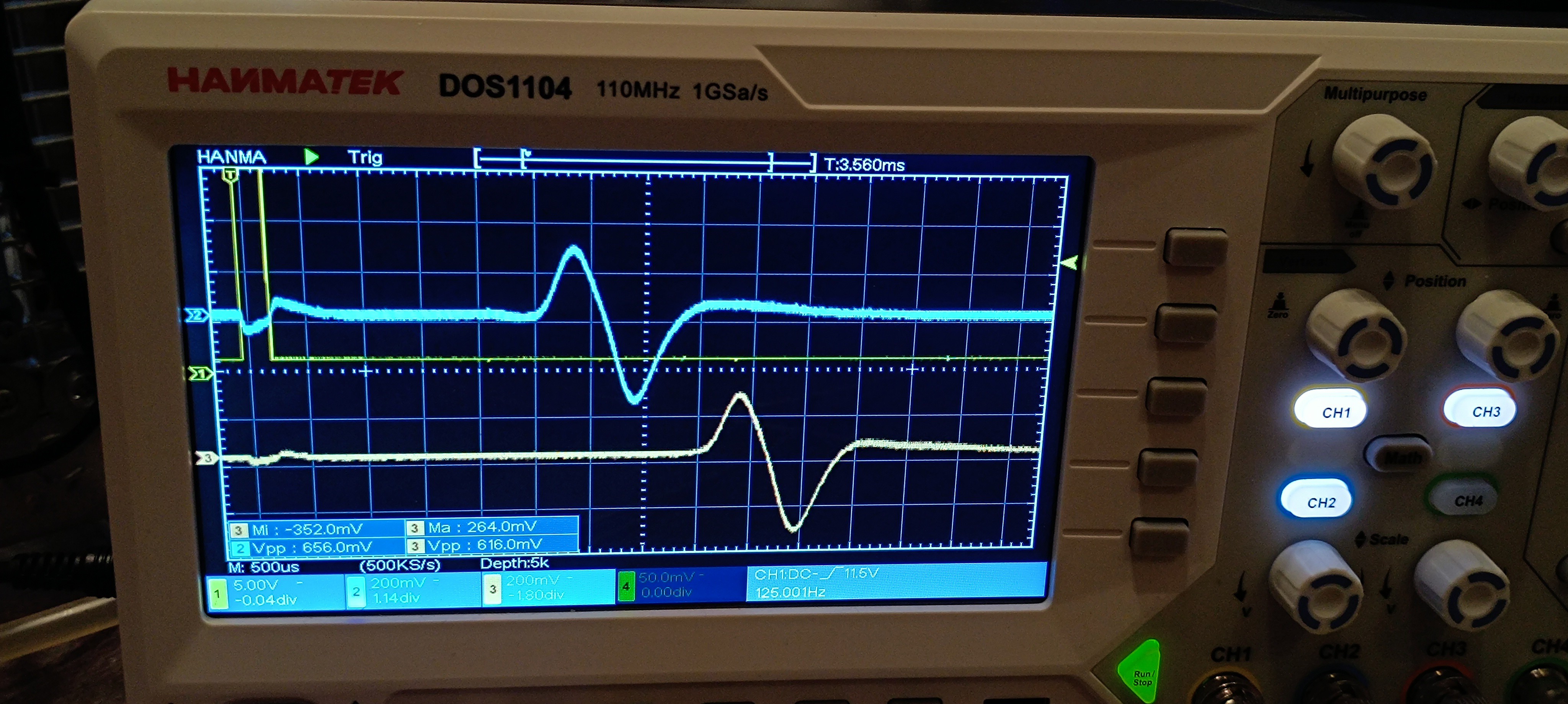
To verify that the amplifier works, I did a quick test of the new amplifier by applying a 0.1V 20kHz signal and looking at the amplifier's output.
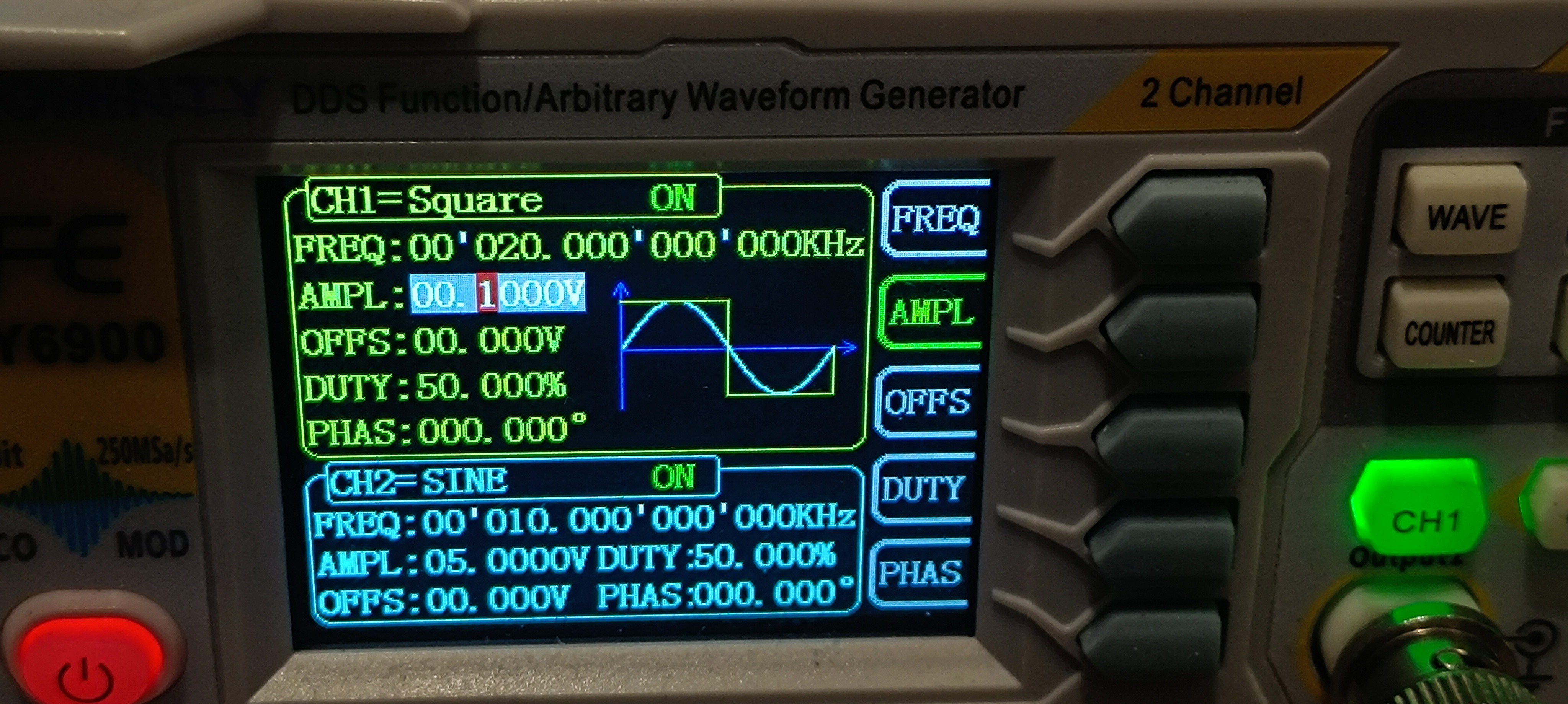

The test showed that the amplifier is turning the sent 0.1V square wave signal into a 0.25V triangle wave.
While I didn't expect the output signal to be a triangle wave and I also thought that the amplification would be a bit higher, the test showed that the built circuit was working.
So, I built a sensor out of a UHF connector that I connected to the amplifier for detecting the charge on the droplets and applied a test signal to the charge electrode.


Conclusion after the first Test:
For now, it looks like it's possible to send a test signal to the charge electrode and receive a feedback signal through the amplifier.
This is an improvement compared to the AD620 amplifier that I have used so far since the old amplifier only worked randomly, and most of the time, it didn't work at all.
The new amplifier, however, is working pretty reliably so far.
Here is a short video of the test:
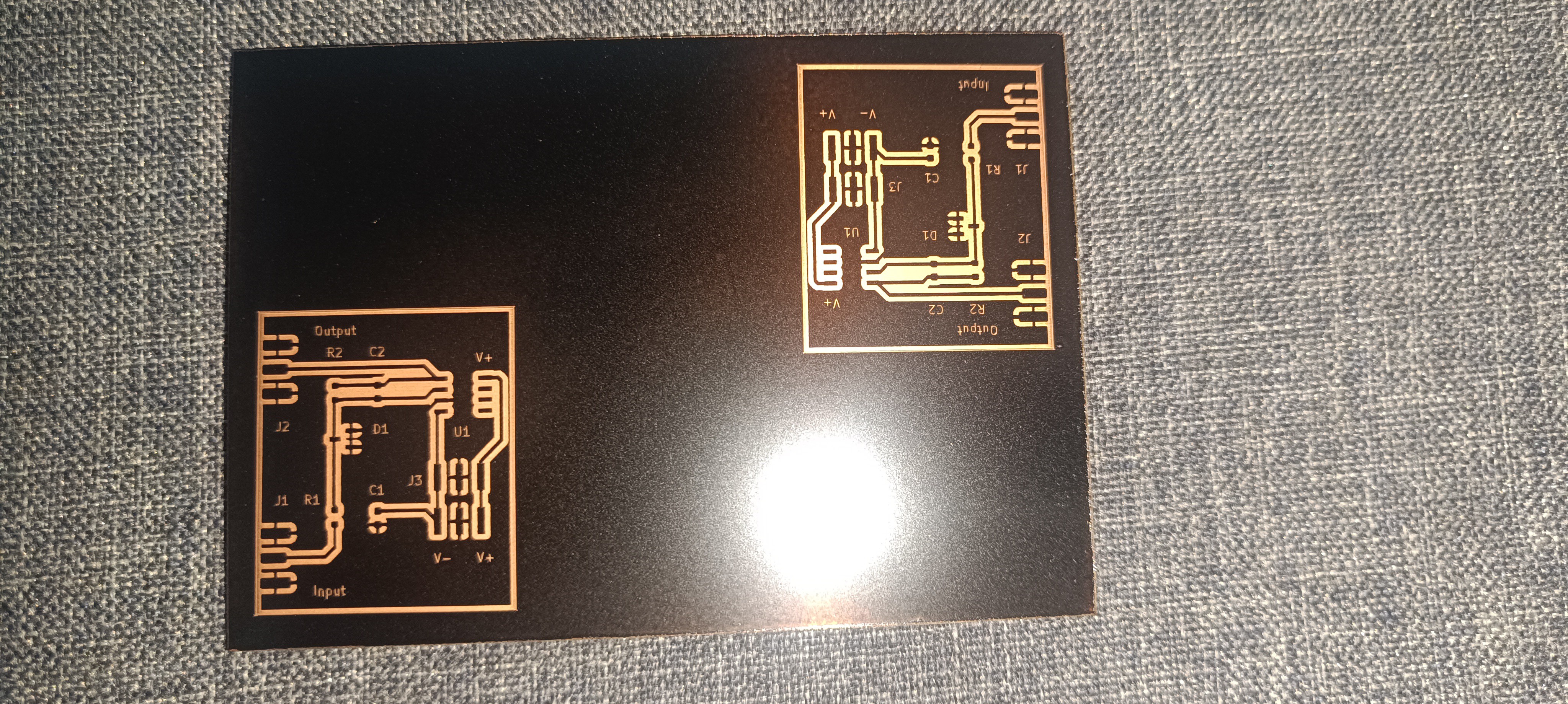
At the moment of writing this, I already built another one and added a TDA2030 amplifier and a high-pass filter to each one of the two to further amplify the signal and filter out the 50Hz mains frequency.
I also built a new sensor assembly made out of a PCB. The new one provides two sensors with a fixed distance between them so that the jet velocity can be calculated by using the known distance and the measured time delay between the signal appearing on the first sensor and the signal appearing on the second sensor.

The next step would be building a peak detector to get the signals ready for feeding them into a microcontroller to measure the time delay.
When that's done, it should be possible to get a stream velocity reading, which would be the first real progress on the printhead driver electronics.
After that, the same circuit could be used to test for the phase shift that works best for charging, but the current amplifier design is too slow to detect groups of charged droplets at the needed frequency.
So, a redesign of the amplifier circuit would be needed before it's ready for this test.
Discussions
Become a Hackaday.io Member
Create an account to leave a comment. Already have an account? Log In.